

Question: A5. Connect the circuit shown in Fig. 10.4. Use data switches for the J, K, S (preset) and R (reset) inputs. Connect probe indicators to
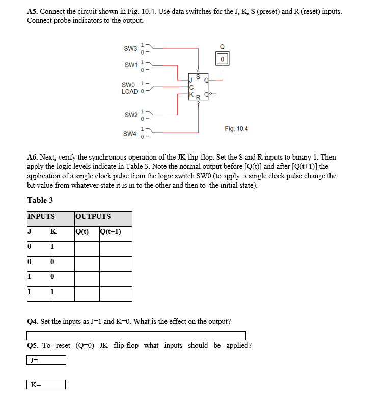
A5. Connect the circuit shown in Fig. 10.4. Use data switches for the J, K, S (preset) and R (reset) inputs. Connect probe indicators to the output. SW36- 0 SW1 1 0- S SWO 1- LOAD O OX R SW2 0- Fig. 10.4 SW4 A6. Next, verify the synchronous operation of the JK flip-flop. Set the S and R inputs to binary 1. Then apply the logic levels indicate in Table 3. Note the normal output before [Q(t)] and after [Q(t+1)] the application of a single clock pulse from the logic switch SWO (to apply a single clock pulse change the bit value from whatever state it is in to the other and then to the initial state). Table 3 INPUTS OUTPUTS J K Qct) Q(t+1) 10 1 10 0 1 10 1 Q4. Set the inputs as "=1 and K=0. What is the effect on the output? Q5. To reset (Q=0) JK flip-flop what inputs should be applied? J= K=
Step by Step Solution
There are 3 Steps involved in it

Get step-by-step solutions from verified subject matter experts