

Question: Table 4 INPUT OUTPUT 1- 0- 1 (ON) 0 (OFF) Fig. 1.4 A5. Connect the circuit as shown in Fig. 1.5. With Swi and SW2
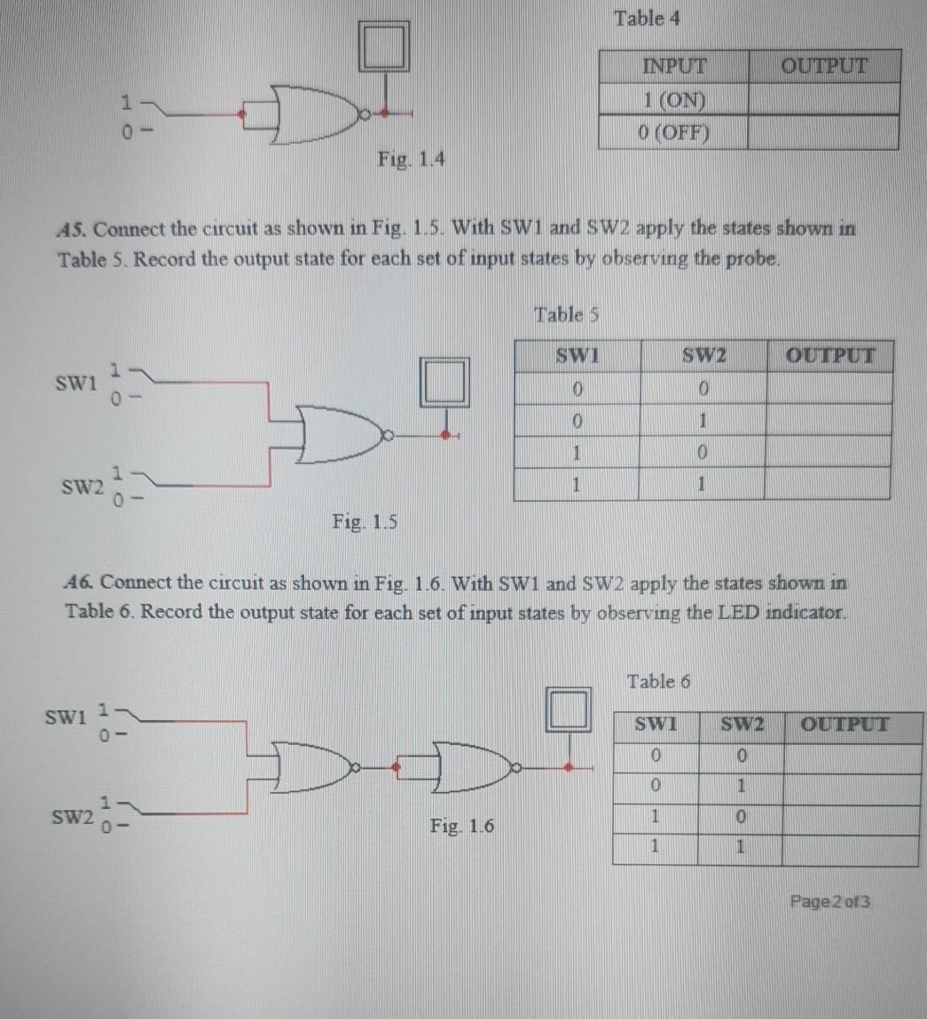
Table 4 INPUT OUTPUT 1- 0- 1 (ON) 0 (OFF) Fig. 1.4 A5. Connect the circuit as shown in Fig. 1.5. With Swi and SW2 apply the states shown in Table 5. Record the output state for each set of input states by observing the probe. Table 5 SWI SW2 OUTPUT SW1 0 O 0 1 1 0 SW2 1 1 1 Fig. 1.5 46. Connect the circuit as shown in Fig. 1.6. With SW1 and SW2 apply the states shown in Table 6. Record the output state for each set of input states by observing the LED indicator. Table 6 SWI 1 SW1 SW2 OUTPUT 0 O 0 1 1 SW2 0- 0 Fig. 1.6 1 1 Page 2 of 3
Step by Step Solution
There are 3 Steps involved in it
1 Expert Approved Answer
Step: 1 Unlock

Question Has Been Solved by an Expert!
Get step-by-step solutions from verified subject matter experts
Step: 2 Unlock
Step: 3 Unlock