

Question: Figure out this Finite State Machine simulation (logism). More specifically on the State Graph, the State Table, then creating a State Assigned Table. Then from
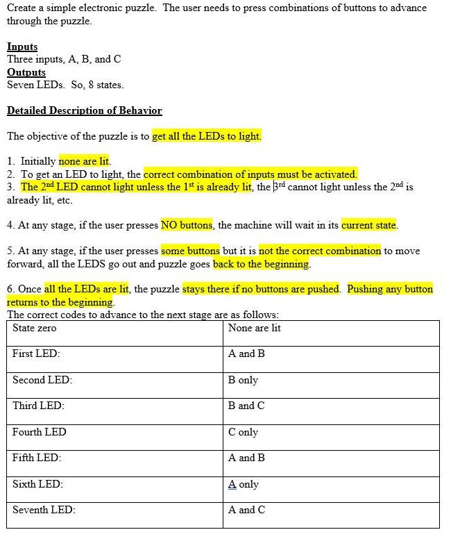
Figure out this Finite State Machine simulation (logism). More specifically on the State Graph, the State Table, then creating a State Assigned Table. Then from there use mainly J-K Flip Flops to create a Excitation Table. Then from Excitation Table derive the K-maps to get the Input Equations, and from State Assigned Table derive the K-maps for the output equations. Lastly, create a schematic or a circuit design for its implementation.
Create a simple electronic puzzle. The user needs to press combinations of buttons to advance through the puzzle. Inputs Three inputs, A, B, and C Outputs Seven LEDs. So, 8 states. Detailed Description of Behavior The objective of the puzzle is to get all the LEDs to light. 1. Initially none are lit. 2. To get an LED to light, the correct combination of inputs must be activated. 3. The 2nd LED cannot light unless the 1st is already lit, the 3rd cannot light unless the 2nd is already lit, etc. 4. At any stage, if the user presses NO buttons, the machine will wait in its current state. 5. At any stage, if the user presses some buttons but it is not the correct combination to move forward, all the LEDS go out and puzzle goes back to the beginning. 6. Once all the LEDs are lit, the puzzle stays there if no buttons are pushed. Pushing any button returns to the beginning. The correct codes to advance to the next stage are as follows: State zero None are lit A and B B only First LED: Second LED: Third LED: Fourth LED Fifth LED: Sixth LED: Seventh LED: B and C C only A and B A only A and C
Step by Step Solution
3.31 Rating (166 Votes )
There are 3 Steps involved in it
Designing a Finite State Machine FSM for this electronic puzzle requires several steps inc... View full answer

Get step-by-step solutions from verified subject matter experts