

Question: ACTIVITY 2: In this activity we simulate a real-life problem of detecting tilt of a machine. We connect a tilt sensor to the input pin
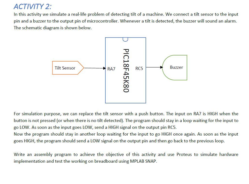
ACTIVITY 2: In this activity we simulate a real-life problem of detecting tilt of a machine. We connect a tilt sensor to the input pin and a buzzer to the output pin of microcontroller. Whenever a tilt is detected, the buzzer will sound an alarm. The schematic diagram is shown below. Tilt Sensor RAZ RC5 Buzzer PIC18F45K80 For simulation purpose, we can replace the tilt sensor with a push button. The input on RAZ is HIGH when the button is not pressed (or when there is no tilt detected). The program should stay in a loop waiting for the input to go LOW. As soon as the input goes LOW, send a HIGH signal on the output pin RC5. Now the program should stay in another loop waiting for the input to go HIGH once again. As soon as the input goes HIGH, the program should send a LOW signal on the output pin and then go back to the previous loop. Write an assembly program to achieve the objective of this activity and use Proteus to simulate hardware implementation and test the working on breadboard using MPLAB SNAP. ACTIVITY 2: In this activity we simulate a real-life problem of detecting tilt of a machine. We connect a tilt sensor to the input pin and a buzzer to the output pin of microcontroller. Whenever a tilt is detected, the buzzer will sound an alarm. The schematic diagram is shown below. Tilt Sensor RAZ RC5 Buzzer PIC18F45K80 For simulation purpose, we can replace the tilt sensor with a push button. The input on RAZ is HIGH when the button is not pressed (or when there is no tilt detected). The program should stay in a loop waiting for the input to go LOW. As soon as the input goes LOW, send a HIGH signal on the output pin RC5. Now the program should stay in another loop waiting for the input to go HIGH once again. As soon as the input goes HIGH, the program should send a LOW signal on the output pin and then go back to the previous loop. Write an assembly program to achieve the objective of this activity and use Proteus to simulate hardware implementation and test the working on breadboard using MPLAB SNAP
Step by Step Solution
There are 3 Steps involved in it

Get step-by-step solutions from verified subject matter experts