

Question: Adder and Subtracter Circuit OBJECTIVES 1. To study the operation of basic adders and subtracters 2. To construct simple adders and subtracters 3. To design
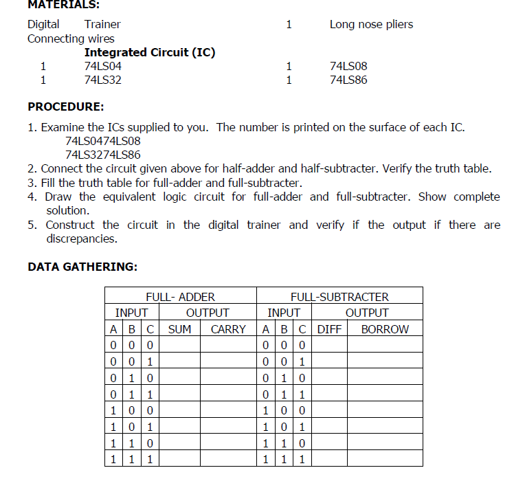
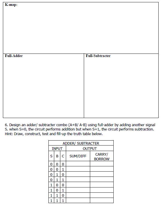
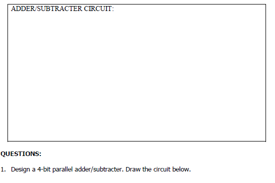
Adder and Subtracter Circuit OBJECTIVES 1. To study the operation of basic adders and subtracters 2. To construct simple adders and subtracters 3. To design adders or subracters for digital application. 1 Long nose pliers MATERIALS: Digital Trainer Connecting wires Integrated Circuit (IC) 1 74LS04 1 74LS32 1 1 74LS08 74L586 PROCEDURE: 1. Examine the ICs supplied to you. The number is printed on the surface of each IC. 74LS0474LS08 74LS3274L586 2. Connect the circuit given above for half-adder and half-subtracter. Verify the truth table. 3. Fill the truth table for full-adder and full-subtracter. 4. Draw the equivalent logic circuit for full-adder and full-subtracter. Show complete solution. 5. Construct the circuit in the digital trainer and verify if the output if there are discrepancies. DATA GATHERING: FULL- ADDER INPUT OUTPUT | A | B | SUM CARRY 0 0 0 001 010 011 1 0 0 1 0 1 1 10 1 11 FULL-SUBTRACTER INPUT OUTPUT A B C DIFF BORROW 000 001 010 011 1 0 0 101 1 1 0 1 11 K-map: Full-Adder Full-Subtracter 6. Design an adder/ subtracter combo (A+B/ A-B) using full-adder by adding another signal S. when S=0, the circuit performs addition but when S=1, the circuit performs subtraction. Hint: Draw, construct, test and fill-up the truth table below. ADDER/ SUBTRACTER INPUT OUTPUT SBC SUM/DIFF CARRY/ BORROW 0 0 0 001 01 0 011 1 0 0 1 0 1 110 11 1 ADDER/SUBTRACTER CIRCUIT: QUESTIONS: 1. Design a 4-bit parallel adder/subtracter. Draw the circuit below. Adder and Subtracter Circuit OBJECTIVES 1. To study the operation of basic adders and subtracters 2. To construct simple adders and subtracters 3. To design adders or subracters for digital application. 1 Long nose pliers MATERIALS: Digital Trainer Connecting wires Integrated Circuit (IC) 1 74LS04 1 74LS32 1 1 74LS08 74L586 PROCEDURE: 1. Examine the ICs supplied to you. The number is printed on the surface of each IC. 74LS0474LS08 74LS3274L586 2. Connect the circuit given above for half-adder and half-subtracter. Verify the truth table. 3. Fill the truth table for full-adder and full-subtracter. 4. Draw the equivalent logic circuit for full-adder and full-subtracter. Show complete solution. 5. Construct the circuit in the digital trainer and verify if the output if there are discrepancies. DATA GATHERING: FULL- ADDER INPUT OUTPUT | A | B | SUM CARRY 0 0 0 001 010 011 1 0 0 1 0 1 1 10 1 11 FULL-SUBTRACTER INPUT OUTPUT A B C DIFF BORROW 000 001 010 011 1 0 0 101 1 1 0 1 11 K-map: Full-Adder Full-Subtracter 6. Design an adder/ subtracter combo (A+B/ A-B) using full-adder by adding another signal S. when S=0, the circuit performs addition but when S=1, the circuit performs subtraction. Hint: Draw, construct, test and fill-up the truth table below. ADDER/ SUBTRACTER INPUT OUTPUT SBC SUM/DIFF CARRY/ BORROW 0 0 0 001 01 0 011 1 0 0 1 0 1 110 11 1 ADDER/SUBTRACTER CIRCUIT: QUESTIONS: 1. Design a 4-bit parallel adder/subtracter. Draw the circuit below
Step by Step Solution
There are 3 Steps involved in it

Get step-by-step solutions from verified subject matter experts