Question: Advanced Heat Transfer - Performance Evaluation Criteria (PEC) for Single Phase Flow I am in need of assistance with solving the below applied heat transfer
Advanced Heat Transfer - Performance Evaluation Criteria (PEC) for Single Phase Flow I am in need of assistance with solving the below applied heat transfer problem scenario. When producing your results, please provide the following six elements (listed 1-6 below). Also, please ensure all data, information, and screenshots are visible when solution is sent back to student (sometimes screenshots provided by tutors get cut-off within Course Hero portal upload). I look forward to learning from you. Thank you for the help! (1) a brief summary of the problem statement
(2) a list of the knowns
(3) a list or brief description of what is to be solved or found
(4) a list of the assumptions that are necessary to solve the problem
(5) an analysis section that shows all work
(6) a conclusion section that summarizes the results
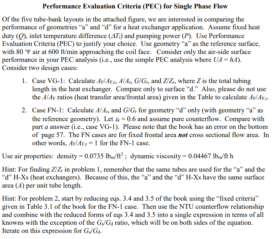
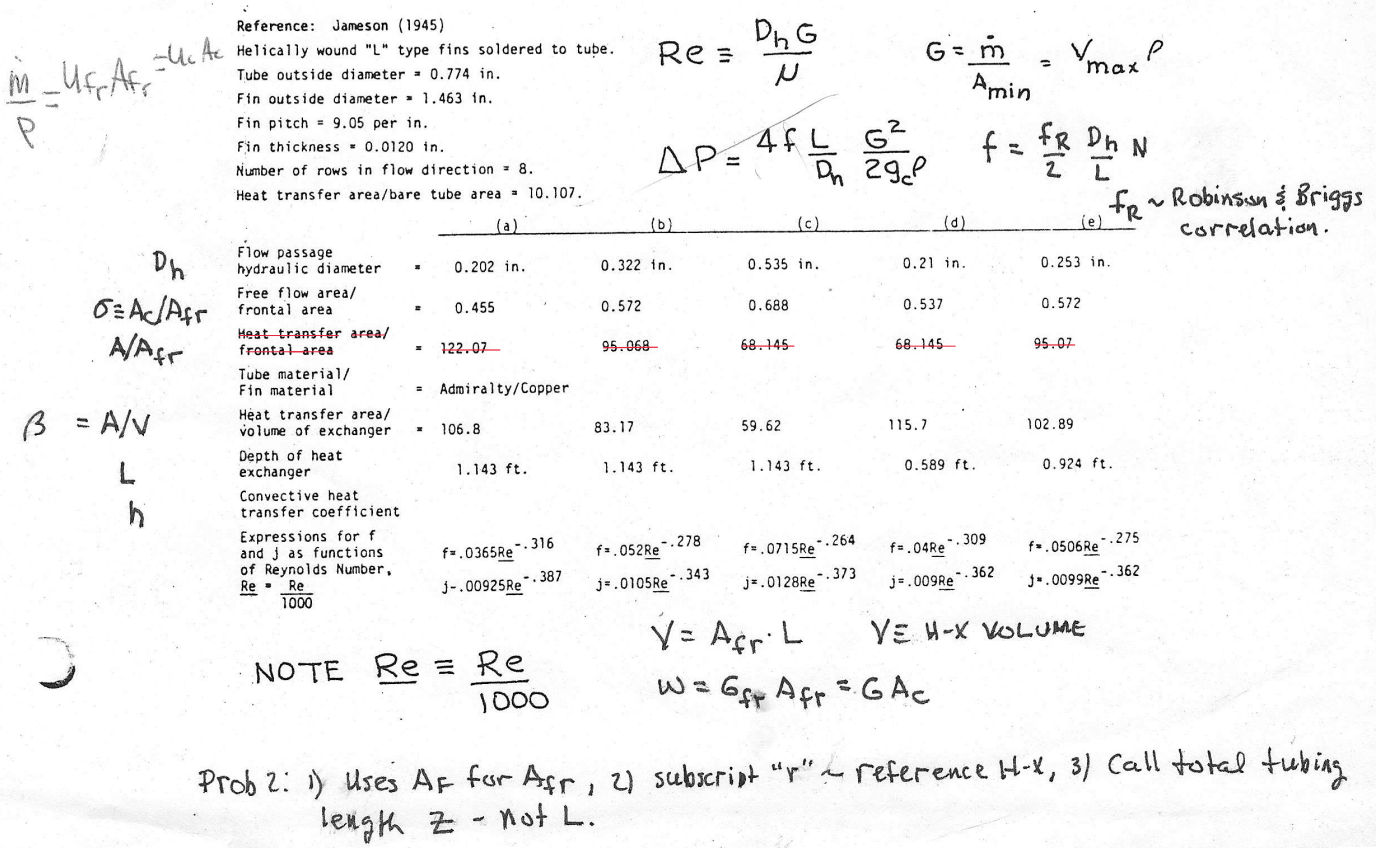
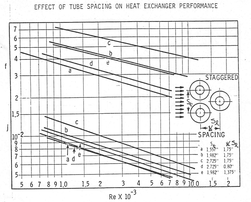
Performance Evaluation Criteria (PEC) for Single Phase Flow Of the five tube-bank layouts in the attached figure, we are interested in comparing the performance of geometries \"a\" and \"d\" for a heat exchanger application. Assume fixed heat duty (Q), inlet temperature difference (A7;) and pumping power (P). Use Performance Evaluation Criteria (PEC) to justify your choice. Use geometry \"a\" as the reference surface, with 80 F air at 600 ft/min approaching the coil face. Consider only the air-side surface performance in your PEC analysis (i.e., use the simple PEC analysis where UA = hA). Consider two design cases: 1. Case VG-1: Calculate Ar/Ap,, A/A;, G/G;, and Z/Z,, where Z is the total tubing length in the heat exchanger. Compare only to surface \"d.\" Also, please do not use the 4/4r ratios (heat transfer area/frontal area) given in the Table to calculate Ar/Ary. 2. Case FN-1: Calculate 4/A,, and G/G, for geometry \"d\" only (with geometry \"a\" as the reference geometry). Let = 0.6 and assume pure counterflow. Compare with part a answer (i.e., case VG-1). Please note that the book has an error on the bottom of page 57. The FN cases are for fixed frontal area not cross sectional flow area. In other words, Ar/Ar,x = 1 for the FN-1 case. Use air properties: density = 0.0735 lb/ft? ; dynamic viscosity = 0.04467 lb/ft h Hint: For finding Z/Z, in problem 1, remember that the same tubes are used for the \"a\" and the \"d\" H-Xs (heat exchangers). Because of this, the \"a\" and the \"d\" H-Xs have the same surface area (A) per unit tube length. Hint: For problem 2, start by reducing eqs. 3.4 and 3.5 of the book using the \"fixed criteria\" given in Table 3.1 of the book for the FN-1 case. Then use the NTU counterflow relationship and combine with the reduced forms of eqs 3.4 and 3.5 into a single expression in terms of all knowns with the exception of the Ga/Ga ratio, which will be on both sides of the equation. Iterate on this expression for Ga/Gua. Reference: Jameson (1945) Uc Ac Helically wound "L" type fins soldered to tube. Re = DIG i _ufpAFS Tube outside diameter = 0.774 in. N G = m = max P Fin outside diameter = 1. 463 in. Amin P Fin pitch = 9.05 per in. Fin thickness = 0.0120 in. AP= 4fL 62 f = FR Dh N Number of rows in flow direction = 8. On 29P 2 I Heat transfer area/bare tube area = 10. 107. (e FR~ Robinson & Briggs (a ) (b) (c) (d ) correlation . Dh Flow passage hydraulic diameter 0. 202 in. 0. 322 in. 0.535 in. 0.21 in. 0. 253 in. Free flow area/ O=AC/Afr frontal area 0. 455 0.572 0. 688 0.537 0. 572 Heat transfer area/ A/Afr frontal area 122. 07 95. 068 68. 145- 68. 145- 95 07 Tube material/ Fin material Admiralty /Copper B = A /V Heat transfer area/ volume of exchanger - 106.8 83. 17 59. 62 115.7 102. 89 Depth of heat L exchanger 1. 143 ft. 1. 143 ft. 1. 143 ft. 0. 589 ft. 0. 924 ft. Convection heat hi transfer coefficient Expressions for f and j as functions f= . 0365Re " . 316 f= . 052Re -. 278 f= . 0715Re - . 264 f= . 04Re" . 309 f= . 0506Re" . 275 of Reynolds Number. Re . Re J- . 00925Re - . 387 j= . 0105Re" - . 343 j= . 0128Re " . 373 j= . 009Re A " . 362 J= . 0099Re " . 362 1000 Y = Afr. L YE H-X VOLUME NOTE Re = Re 1000 W = GSP Afr = GAc Prob 2: 1) Uses AF for Afr, 21 subscript "r" ~ reference H-X, 3/ Call total tubing length Z - not L.EFFECT OF TUBE SPACING ON HEAT EXCHANGER PERFORMANCE C A VIA d e a W STAGGERED 2 15 C b -2. SPACING SE a 1.557" 1.75" Ula NOOO ad b 1.982"' 1.75" C 2.725" 1.75" d 2.725" 0.80' e 1.982" 1,375" 5 6 7 8 910 1.5 2 3 4 5 6 7 8 9 10 0 15 2 Re X 10 3
Step by Step Solution
There are 3 Steps involved in it
1 Expert Approved Answer
Step: 1 Unlock
Question Has Been Solved by an Expert!
Get step-by-step solutions from verified subject matter experts
Step: 2 Unlock
Step: 3 Unlock
Students Have Also Explored These Related Accounting Questions!