

Question: Agas stored in a large reservoir (or combustion chamber) (Fig. 1) is to be discharged through a converging nozzle. For a constant reservoir pressure
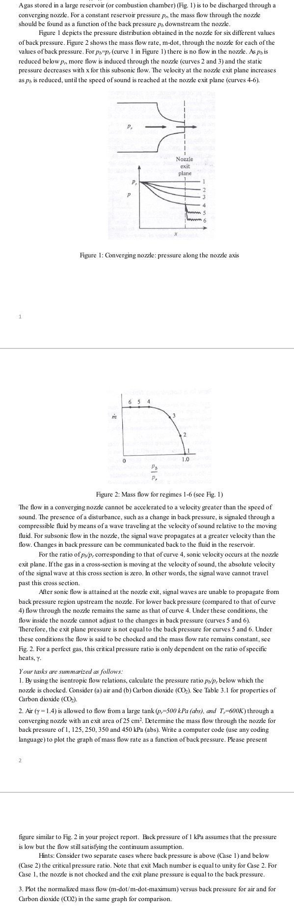
Agas stored in a large reservoir (or combustion chamber) (Fig. 1) is to be discharged through a converging nozzle. For a constant reservoir pressure p,, the mass flow through the nozzle should be found as a function of the back pressure p, downstream the nozzle. Figure 1 depicts the pressure distribution obtained in the nozzle for six different values of back pressure. Figure 2 shows the mass flow rate, m-dot, through the nozzle for each of the values of back pressure. For ph-p, (curve 1 in Figure 1) there is no flow in the nozzle. As pis reduced below p,, more flow is induced through the nozzle (curves 2 and 3) and the static pressure decreases with x for this subsonic flow. The velocity at the nozzle exit plane increases as p, is reduced, until the speed of sound is reached at the nozzle exit plane (curves 4-6). 1 Nozzle exit plane P. P 3 4 5 Figure 1: Converging nozzle: pressure along the nozzle axis m 6 5 4 2 1 0 1.0 Figure 2: Mass flow for regimes 1-6 (see Fig. 1) The flow in a converging nozzle cannot be accelerated to a velocity greater than the speed of sound. The presence of a disturbance, such as a change in back pressure, is signaled through a compressible fluid by means of a wave traveling at the velocity of sound relative to the moving fluid. For subsonic flow in the nozzle, the signal wave propagates at a greater velocity than the flow. Changes in back pressure can be communicated back to the fluid in the reservoir. For the ratio of p/p, corresponding to that of curve 4, sonic velocity occurs at the nozzle exit plane. If the gas in a cross-section is moving at the velocity of sound, the absolute velocity of the signal wave at this cross section is zero. In other words, the signal wave cannot travel past this cross section. After sonic flow is attained at the nozzle exit, signal waves are unable to propagate from back pressure region upstream the nozzle. For lower back pressure (compared to that of curve 4) flow through the nozzle remains the same as that of curve 4. Under these conditions, the flow inside the nozzle cannot adjust to the changes in back pressure (curves 5 and 6). Therefore, the exit plane pressure is not equal to the back pressure for curves 5 and 6. Under these conditions the flow is said to be chocked and the mass flow rate remains constant, see Fig. 2. For a perfect gas, this critical pressure ratio is only dependent on the ratio of specific heats, Y. Your tasks are summarized as follows: 1. By using the isentropic flow relations, calculate the pressure ratio p/p, below which the nozzle is chocked. Consider (a) air and (b) Carbon dioxide (CO2). See Table 3.1 for properties of Carbon dioxide (CO2). 2. Air (y =1.4) is allowed to flow from a large tank (p,-500 kPa (abs), and T-600K) through a converging nozzle with an exit area of 25 cm. Determine the mass flow through the nozzle for back pressure of 1, 125, 250, 350 and 450 kPa (abs). Write a computer code (use any coding language) to plot the graph of mass flow rate as a function of back pressure. Please present 2 figure similar to Fig. 2 in your project report. Back pressure of 1 kPa assumes that the pressure is low but the flow still satisfying the continuum assumption. Hints: Consider two separate cases where back pressure is above (Case 1) and below (Case 2) the critical pressure ratio. Note that exit Mach number is equal to unity for Case 2. For Case 1, the nozzle is not chocked and the exit plane pressure is equal to the back pressure. 3. Plot the normalized mass flow (m-dot/m-dot-maximum) versus back pressure for air and for Carbon dioxide (CO2) in the same graph for comparison.
Step by Step Solution
There are 3 Steps involved in it

Get step-by-step solutions from verified subject matter experts