

Question: ALU Description Inputs: - Data A ( 4 - bits ) - Data B ( 4 - bits ) - Mode ( 1 - bit
ALU Description
Inputs:
Data A bits
Data B bits
Mode bit
Selection bits
Outputs:
Operation Results F bits
Comparator Results bits
Carry Out bits One bit for Addition operation and one bit for Subtraction operation
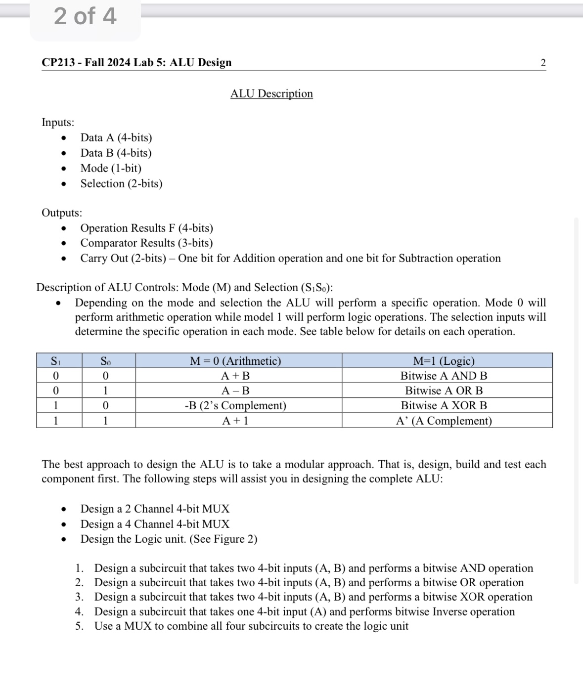
Description of ALU Controls: Mode M and Selection mathrmSmathrm~S:
Depending on the mode and selection the ALU will perform a specific operation. Mode will perform arithmetic operation while model will perform logic operations. The selection inputs will determine the specific operation in each mode. See table below for details on each operation.
The best approach to design the ALU is to take a modular approach. That is design, build and test each component first. The following steps will assist you in designing the complete ALU:
Design a Channel bit MUX
Design a Channel bit MUX
Design the Logic unit. See Figure
Design a subcircuit that takes two bit inputs A B and performs a bitwise AND operation
Design a subcircuit that takes two bit inputs A B and performs a bitwise OR operation
Design a subcircuit that takes two bit inputs A B and performs a bitwise XOR operation
Design a subcircuit that takes one bit input A and performs bitwise Inverse operation
Use a MUX to combine all four subcircuits to create the logic unit
Step by Step Solution
There are 3 Steps involved in it
1 Expert Approved Answer
Step: 1 Unlock

Question Has Been Solved by an Expert!
Get step-by-step solutions from verified subject matter experts
Step: 2 Unlock
Step: 3 Unlock