

Question: Design a specialized driver for a 7-segment display that works as follows: When the input to the system is 1, output is A When the
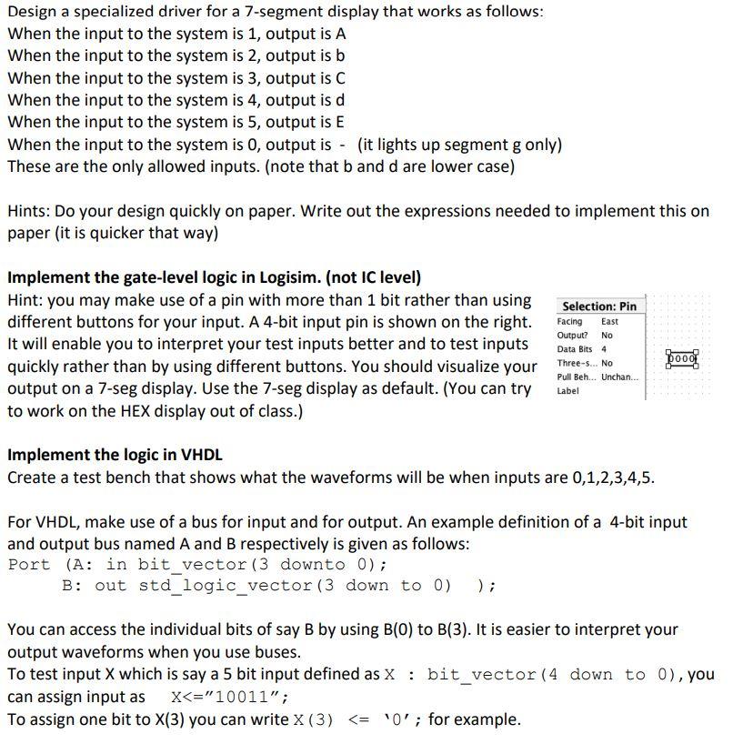
Design a specialized driver for a 7-segment display that works as follows: When the input to the system is 1, output is A When the input to the system is 2, output is b When the input to the system is 3, output is C When the input to the system is 4, output is d When the input to the system is 5, output is E When the input to the system is 0, output is - (it lights up segment g only) These are the only allowed inputs. (note that b and d are lower case) Hints: Do your design quickly on paper. Write out the expressions needed to implement this on paper (it is quicker that way) East Implement the gate-level logic in Logisim. (not IC level) Hint: you may make use of a pin with more than 1 bit rather than using Selection: Pin different buttons for your input. A 4-bit input pin is shown on the right. Facing Output? No It will enable you to interpret your test inputs better and to test inputs Data Bits 4 quickly rather than by using different buttons. You should visualize your Three-.NO output on a 7-seg display. Use the 7-seg display as default. (You can try Label to work on the HEX display out of class.) pood Pull Beh... Unchan... Implement the logic in VHDL Create a test bench that shows what the waveforms will be when inputs are 0,1,2,3,4,5. For VHDL, make use of a bus for input and for output. An example definition of a 4-bit input and output bus named A and B respectively is given as follows: Port (A: in bit_vector (3 downto 0); B: out std_logic_vector (3 down to 0) ); You can access the individual bits of say B by using B(0) to B(3). It is easier to interpret your output waveforms when you use buses. To test input X which is say a 5 bit input defined as X : bit_vector (4 down to 0), you can assign input as X
Step by Step Solution
There are 3 Steps involved in it

Get step-by-step solutions from verified subject matter experts