

Question: answer the following below with c;;;;;om......pl//e.te ans. each, thank you. stimulator link: https://phet.colorado.edu/sims/html/circuit-construction-kit-dc/latest/circuit-construction-kit-dc_en.html 1. Click the INTRO 2. Check the box on the right to
answer the following below with c;;;;;om......pl//e.te ans. each, thank you. stimulator link:
https://phet.colorado.edu/sims/html/circuit-construction-kit-dc/latest/circuit-construction-kit-dc_en.html
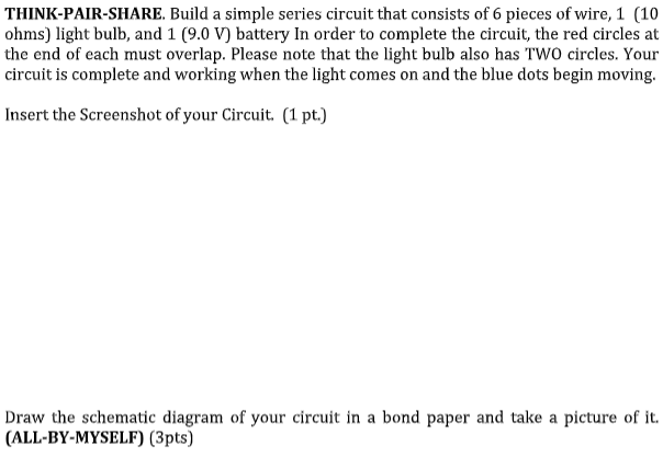
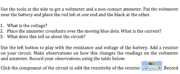
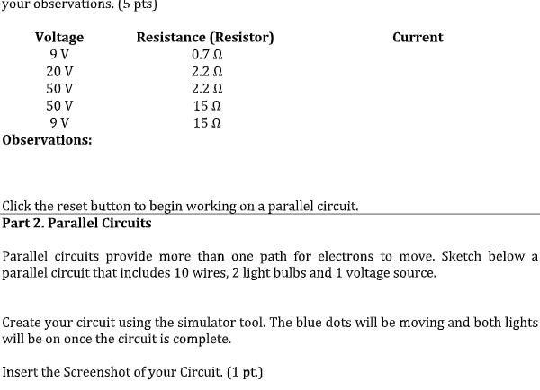
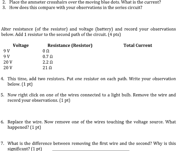
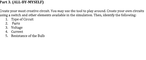
1. Click the "INTRO" 2. Check the box on the right to show current (electron), labels and values. 3. You now have the raw material to create a circuit. Take a moment to look over the site and find all the different materials. To build a circuit you will need several wires, a light bulb, a voltage source, a voltmeter, and a non - contact ammeter. Play with it to see how to grab and manipulate these tools. 4. Click the reset button OTHINK-PAIR-SHARE. Build a simple series circuit that consists of 6 pieces of wire, 1 (10 ohms) light bulb, and 1 (9.0 V) battery In order to complete the circuit, the red circles at the end of each must overlap. Please note that the light bulb also has TWO circles. Your circuit is complete and working when the light comes on and the blue dots begin moving. Insert the Screenshot of your Circuit. (1 pt.) Draw the schematic diagram of your circuit in a bond paper and take a picture of it. (ALL-BY-MYSELF) (3pts)Use the tools at the side to get a voltmeter and a non-contact ammeter. Put the voltmeter near the battery and place the red tab at one end and the black at the other. 1. What is the voltage? 2. Place the ammeter crosshairs over the moving blue dots. What is the current? 3. What does this tell us about the circuit? Use the left button to play with the resistance and voltage of the battery. Add a resistor on your circuit. Make observations on how this changes the readings on the voltmeter and ammeter. Record your observations using the table below. Click the component of the circuit to edit the resistivity of the resistor Recordyour observations. (5 pts) Voltage Resistance (Resistor) Current 9 V 0.70 20 V 2.2 0 50 V 2.2 0 50 V 15 0 9V 15 0 Observations: Click the reset button to begin working on a parallel circuit. Part 2. Parallel Circuits Parallel circuits provide more than one path for electrons to move. Sketch below a parallel circuit that includes 10 wires, 2 light bulbs and 1 voltage source. Create your circuit using the simulator tool. The blue dots will be moving and both lights will be on once the circuit is complete. Insert the Screenshot of your Circuit. (1 pt.)Draw the schematic diagram of your circuit in a bond paper and take a picture of it. (ALL-BY-MYSELF) (3 pts) Use the voltmeter and non-contact ammeter to measure electron flow and push. 1. What is the voltage?2. Place the ammeter crosshairs over the moving blue dots. What is the current? 3. How does this compare with your observations in the series circuit? Alter resistance (of the resistor) and voltage (battery) and record your observations below. Add 1 resistor to the second path of the circuit. (4 pts) Voltage Resistance (Resistor) Total Current 9 V on 9 V 0.7 0 20 V 2.2 0 20 V 21 0 4. This time, add two resistors. Put one resistor on each path. Write your observation below. (1 pt] 5. Now right click on one of the wires connected to a light bulb. Remove the wire and record your observations. (1 pt] 6. Replace the wire. Now remove one of the wires touching the voltage source. What happened? (1 pt) 7. What is the difference between removing the first wire and the second? Why is this significant? (1 pt)Part 3. (ALL-BY-MYSELF) Create your most creative circuit. You may use the tool to play around. Create your own circuits using a switch and other elements available in the simulation. Then, identify the following: 1. Type of Circuit 2. Parts 3. Voltage 4. Current 5. Resistance of the Bulb
Step by Step Solution
There are 3 Steps involved in it

Get step-by-step solutions from verified subject matter experts