

Question: As shown in Fig. P-269, there is a gap between the aluminum bar and the rigid slab that is supported by two copper bars.
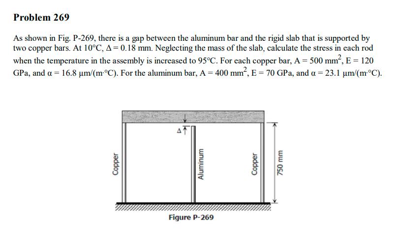
As shown in Fig. P-269, there is a gap between the aluminum bar and the rigid slab that is supported by two copper bars. At 10C, A = 0.18 mm. Neglecting the mass of the slab, calculate the stress in each rod when the temperature in the assembly is increased to 95C. For each copper bar, A = 500 mm, E = 120 GPa, and a = 16.8 m/(m C). For the aluminum bar, A = 400 mm, E = 70 GPa, and a = 23.1 m/(mC). Copper AT Aluminum Figure P-269 Copper 750 mm
Step by Step Solution
★★★★★
3.46 Rating (156 Votes )
There are 3 Steps involved in it
1 Expert Approved Answer
Step: 1 Unlock

The detailed ... View full answer
Question Has Been Solved by an Expert!
Get step-by-step solutions from verified subject matter experts
Step: 2 Unlock
Step: 3 Unlock