5. Consider the block diagram of an antenna control system shown in Fig. P 5. This system...
Question:
5. Consider the block diagram of an antenna control system shown in Fig. P 5. This system is described in Section 1.5 . Let T = 0.05 and the sensor gain be unity (H = 1).
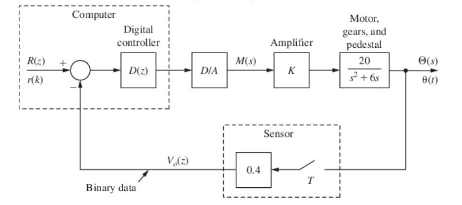
Figure P 5 Block diagram for an antenna control system.Figure P8.6-5 Full Alternative TextIt was shown in Problem 7
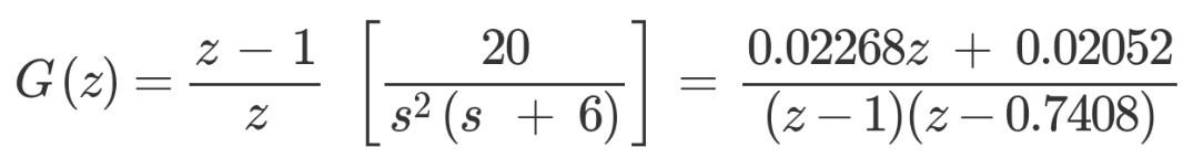
The frequency response for G(z) is given in Table P7-24.
Find the system phase margin with K = 1 and D(z) = 1.
To reduce steady-state errors, K is increased to 5. Design a unity-dc-gain phase-lag controller that yields a system phase margin of 45?.
Design a unity-dc-gain phase-lead controller, with K = 5, that yields a system phase margin of 45?.
Using MATLAB, find the unit step response for the systems of parts (b) and (c). Compare the rise times and the percent overshoot for the two systems...........................................................
8.
Design a PI controller for Problem 5 (b).
Design a PD controller for Problem 5 (e).
Use the results of parts (a) and (b) to repeat Problem 5 (d).
Expert Answer: