

Question: As shown in Figure 1 ( a ) , a clutch is used to connect a driven shaft to a rotating load. The clutch consists
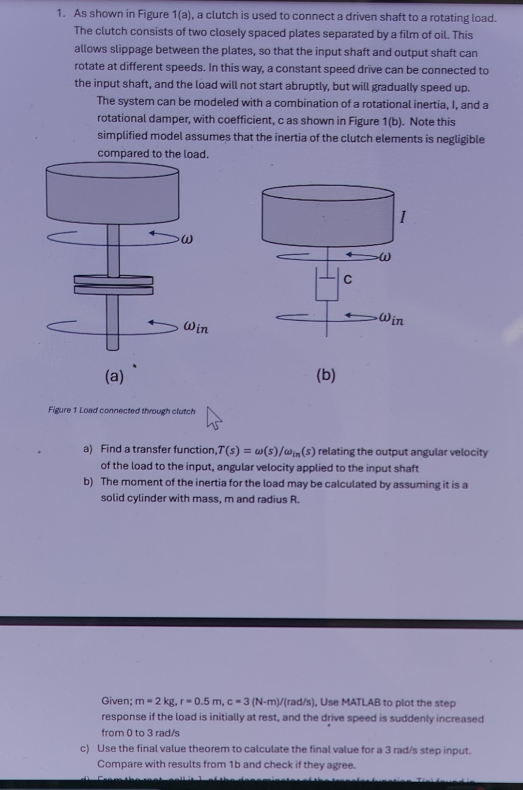
As shown in Figure a a clutch is used to connect a driven shaft to a rotating load.
The clutch consists of two closely spaced plates separated by a fitm of oil. This
allows slippage between the plates, so that the input shaft and output shaft can
rotate at different speeds. In this way, a constant speed drive can be connected to
the input shaft, and the load will not start abruptly, but will gradually speed up
The system can be modeled with a combination of a rotational inertia, I, and a
rotational damper, with coefficient, c as shown in Figure b Note this
simplified model assumes that the inertia of the clutch elements is negligible
a Find a transfer function, relating the output angular velocity
of the load to the input, angular velocity applied to the input shaft
b The moment of the inertia for the load may be calculated by assuming it is a
solid cylinder with mass, and radius
Given; Use MATLAB to plot the step
response if the load is initially at rest, and the drive speed is suddenly increased
from to
c Use the final value theorem to calculate the final value for a step input.
Compare with results from b and check if they agree.
d From the root, call it of the denominator of the transfer function Ts found in
a determine the system time constant, T Reand estimate the settling
time using ts t Check
if the result agrees with your simulated step response.
Step by Step Solution
There are 3 Steps involved in it
1 Expert Approved Answer
Step: 1 Unlock

Question Has Been Solved by an Expert!
Get step-by-step solutions from verified subject matter experts
Step: 2 Unlock
Step: 3 Unlock