

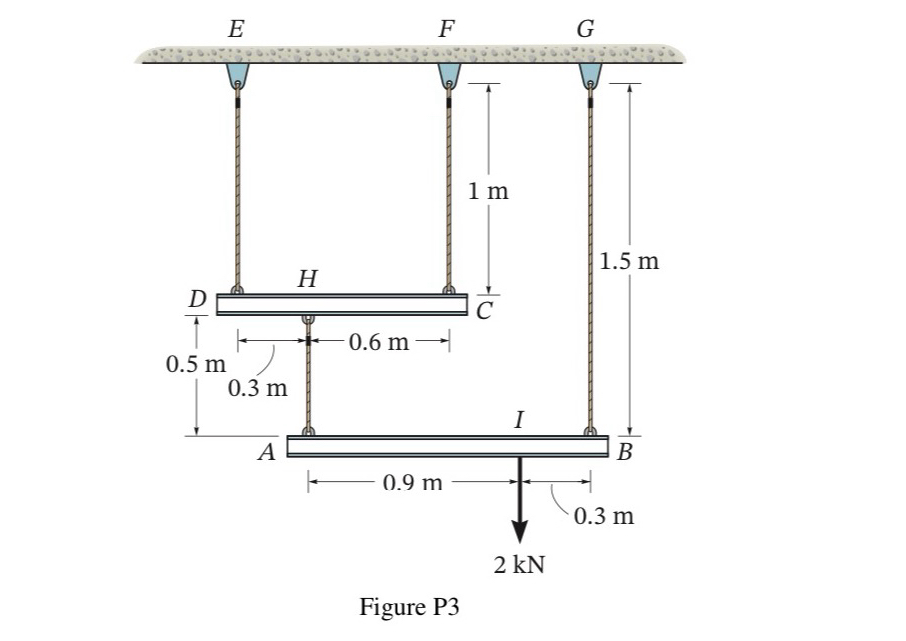
Question: As shown in Figure P 3 , the 2 KN load is supported by 4 stainless steel wires connected to the rigid member AB and
As shown in Figure P the KN load is supported by stainless steel wires connected to the rigid member AB and DC When the k load is applied, find the vertical displacement of the junction I where the load acts. At this time, the crosssectional area A of each wire is mm and the elastic coefficient E of the stainless steel wire is It's GPa.
Step by Step Solution
There are 3 Steps involved in it
1 Expert Approved Answer
Step: 1 Unlock

Question Has Been Solved by an Expert!
Get step-by-step solutions from verified subject matter experts
Step: 2 Unlock
Step: 3 Unlock