

Question: ASAP please 26-7: The ASMchart given in Fig. P6-7 models a FSM (of a control unit). Note that the states in the ASMchart are not
 ASAP please
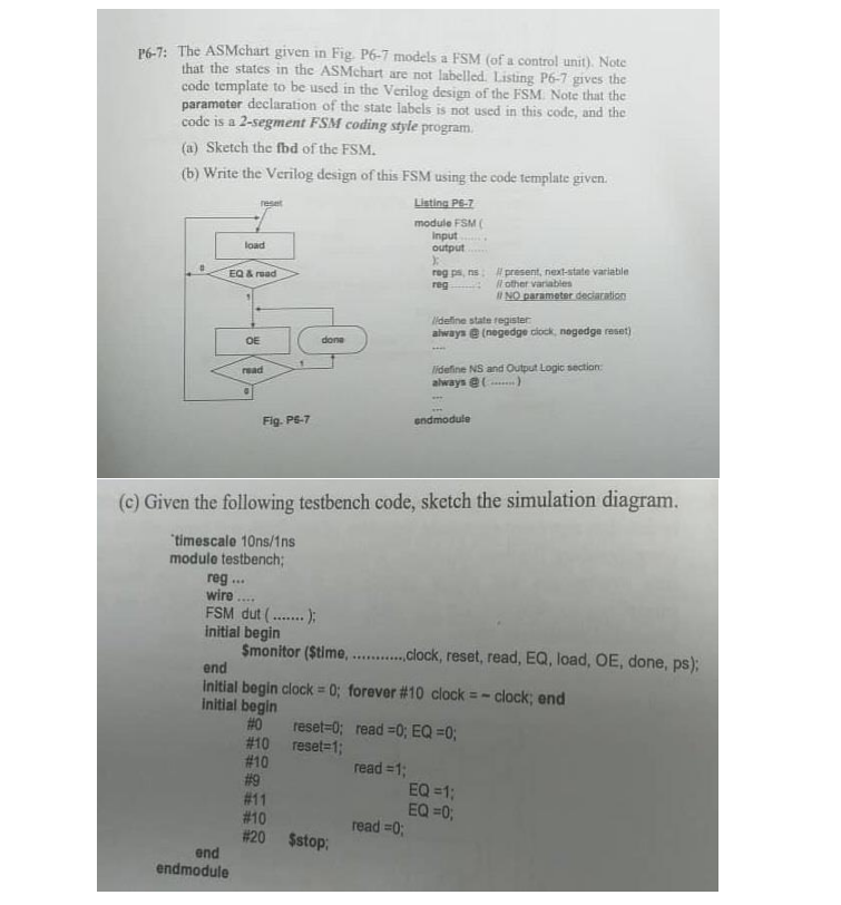
26-7: The ASMchart given in Fig. P6-7 models a FSM (of a control unit). Note that the states in the ASMchart are not labelled Listing P6-7 gives the code template to be used in the Verilog design of the FSM. Note that the parameter declaration of the state labels is not used in this code, and the code is a 2-segment FSM coding style program (a) Sketch the fbd of the FSM. (b) Write the Verilog design of this FSM using the code template given. Listing P6-7 module FSM Input output : rog ps, present, next-state variable reg Il other variables NO parameter declaration Hideline stato register always negedge clock negedga reset) re load EQ & road OE done read lideline NS and Output Logic section: always @......) Fig. P5-7 ondmodule (c) Given the following testbench code, sketch the simulation diagram. "timescalo 10ns/1ns modulo testbench; reg wire... FSM dut (.......); initial begin Smonitor ($time.............clock, reset, read, EQ, load, OE, done, ps); end Initial begin clock = 0; forever #10 clock = - clock; end Initial begin #0 reset=0; read =0; EQ =0; #10 reset=1; #10 read = 1; #9 EQ =1; #11 EQ =0; #10 read =0; #20 $stop; ond endmodule 26-7: The ASMchart given in Fig. P6-7 models a FSM (of a control unit). Note that the states in the ASMchart are not labelled Listing P6-7 gives the code template to be used in the Verilog design of the FSM. Note that the parameter declaration of the state labels is not used in this code, and the code is a 2-segment FSM coding style program (a) Sketch the fbd of the FSM. (b) Write the Verilog design of this FSM using the code template given. Listing P6-7 module FSM Input output : rog ps, present, next-state variable reg Il other variables NO parameter declaration Hideline stato register always negedge clock negedga reset) re load EQ & road OE done read lideline NS and Output Logic section: always @......) Fig. P5-7 ondmodule (c) Given the following testbench code, sketch the simulation diagram. "timescalo 10ns/1ns modulo testbench; reg wire... FSM dut (.......); initial begin Smonitor ($time.............clock, reset, read, EQ, load, OE, done, ps); end Initial begin clock = 0; forever #10 clock = - clock; end Initial begin #0 reset=0; read =0; EQ =0; #10 reset=1; #10 read = 1; #9 EQ =1; #11 EQ =0; #10 read =0; #20 $stop; ond endmodule
Step by Step Solution
There are 3 Steps involved in it

Get step-by-step solutions from verified subject matter experts