

Question: Ask for help design it using DEEDS. Mini Project: Programmable Logic Device (PLD) Photocopying (Xerox) Machine A. Objectives The objectives of this laboratory are to

Ask for help design it using DEEDS.
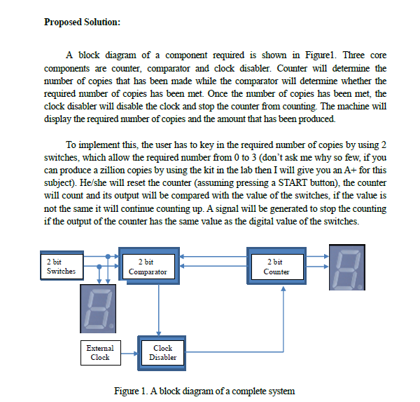
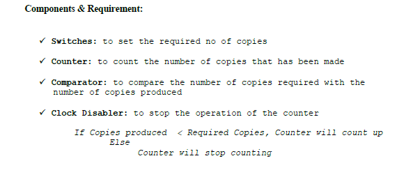
Mini Project: Programmable Logic Device (PLD) Photocopying (Xerox) Machine A. Objectives The objectives of this laboratory are to introduce the students to: The development of a PLD device A simple Hardware Description Language B. Materials Breadboard ATMEL 22V10 - 1 unit ETS-5000 Digital Training kit Wellon or Hi-Lo ALL-11 Universal Programmer & Tester WinCUPL 5.0 Software Handouts: "WinCUPL user manual" "ATMEL22V10 Data Sheet" "How to use Hi-Lo Programmer" "How to use Wellon Programmer" As an appendix in your Lab Book "How to use Win CUPL 5" C. Mini Project: Photocopying (Xerox) Machine Background Read the appendix in your lab book to familiarize yourself with the WinCUPL compiler and the universal programmer. If you need any help please ask your lecturer or the teaching assistants This mini project will implement 3 different components on a single ATMEL device, those components are 1. Count Up Counter 2. Comparator 3. Clock Disabler Problem: User will initially enter amount of copies, the counter will count the number of copies that has been photocopied. The machine will stop once the required number of copies produced Proposed Solution: A block diagram of a component required is shown in Figurel. Three core components are counter, comparator and clock disabler. Counter will determine the number of copies that has been made while the comparator will determine whether the required number of copies has been met. Once the number of copies has been met, the clock disabler will disable the clock and stop the counter from counting. The machine will display the required number of copies and the amount that has been produced. To implement this, the user has to key in the required number of copies by using 2 switches, which allow the required number from 0 to 3 (don't ask me why so few, if you can produce a zillion copies by using the kit in the lab then I will give you an A+ for this subject). He/she will reset the counter (assuming pressing a START button), the counter will count and its output will be compared with the value of the switches, if the value is not the same it will continue counting up. A signal will be generated to stop the counting if the output of the counter has the same value as the digital value of the switches. 2 bit Switches 2 bit Comparator 2 bit Counter External Clock Clock Disabler Figure 1. A block diagram of a complete system Components & Requirement: Switches: to set the required no of copies Counter: to count the number of copies that has been made Comparator: to compare the number of copies required with the number of copies produced Clock Disabler: to stop the operation of the counter If Copies produced
Step by Step Solution
There are 3 Steps involved in it

Get step-by-step solutions from verified subject matter experts