

Question: In this lab, you will design the 3 2 - bit Arithmetic Logic Unit ( ALU ) . It is described in Section 5 .
In this lab, you will design the bit Arithmetic Logic Unit ALU It is described in Section
of the text, but you will design the ALU described in the video lectures and lecture notes. Your
ALU is an important building block of microprocessors. In this lab you will design an ALU in
SystemVerilog. You will also write a SystemVerilog testbench and testvector file to test the ALU.
The design in this lab will demonstrate the ways in which SystemVerilog encoding makes
hardware design more efficient. It is possible to design a bit ALU from bit ALUs ie you
could program a bit ALU incorporating your full adder from Lab chain four of these together
to make a bit ALU, and chain of those together to make a bit ALU. However, it is
altogether more efficient both in time and lines of code to code it succinctly in SystemVerilog.
You will complete the following steps in this lab:
Design an ALU in SystemVerilog
Write a testbench and testvector file to test your ALU
Simulate your ALU using your testbench and testvector file in ModelSim
Create a wrapper module for your ALU that maps the ALU interface to the DE board
peripherals
Synthesize compile ALU in Quartus II and optimize ALU design if needed
Submission Instructions
Remember that you must always simulate your SystemVerilog design before building it in
hardware.
Be sure to read the "What to Turn InSection at the end of the lab before beginning the lab.
Important: Most everyone should be currently enrolled in CpE If you are not currently
enrolled in CpE ie you took it in a prior semester you may view the videos, lecture
slides, and example SystemVerilog files on CPE Ls Canvas page.
As always, be sure to start and finish the lab early so that you have enough time to work through
your issues andor have time to ask for help.
DESign AN ALU IN SYStEMVERILOG
Create a bit ALU in SystemVerilog. Name the file
alu.sv It should have the following module
declaration:
module aluinput logic : A B
input logic : ALUControl,
output logic : Result;Your module should implement the ALU given in the CPE lecture note that this is slightly
different from the ALU in Chapter of the textbook Digital Design and Computer Architecture.
The schematic and truth table for the ALU are shown below. It is recommended that you label
the internal nodes as needed and then declare an internal signal within your module with the
correct bus width.
Table ALU Functionality
WRITE A TESTBENCH AND TESTVECTOR FILE TO TEST YOUR ALU
Now you can test the bit ALU in ModelSim. It is prudent to think through a set of input vectors.
Develop an appropriate set of test vectors to convince a reasonable person that your design is
probably correct. Complete Table to verify that all ALU operations work as they are supposed
to Note that the values are expressed in hexadecimal to reduce the amount of writing. Add at least
four lines at the bottom of the table to test the SLT set if less than operation.
Table ALU operationsBuild a selfchecking testbench to test your bit ALU. To do this, you'll need a file containing
test vectors. Create a file called alu.txt with all your vectors. For example, the file for describing
the first three lines in Table might look like this:
Hint: Remember that each hexadecimal digit in the test vector file represents bits. Be careful
when pulling signals from the file that are not multiples of four bits.
You may use the testbench from Lab testbenchseg.sv as a starting point for designing your
testbench. Name your new testbench testbenchalu.sv Be sure to change the bit widths of the
testvectors.
SIMULATE YOUR ALU TESTBENCH IN MODELSIM
Compile your ALU and testbench in ModelSim and simulate the testbench. Run for a long
enough time to check all of the vectors. If you encounter any errors, correct your design and
rerun. It is a good idea to add a line with an incorrect vector to the end of the test vector file to
verify that the testbench works!
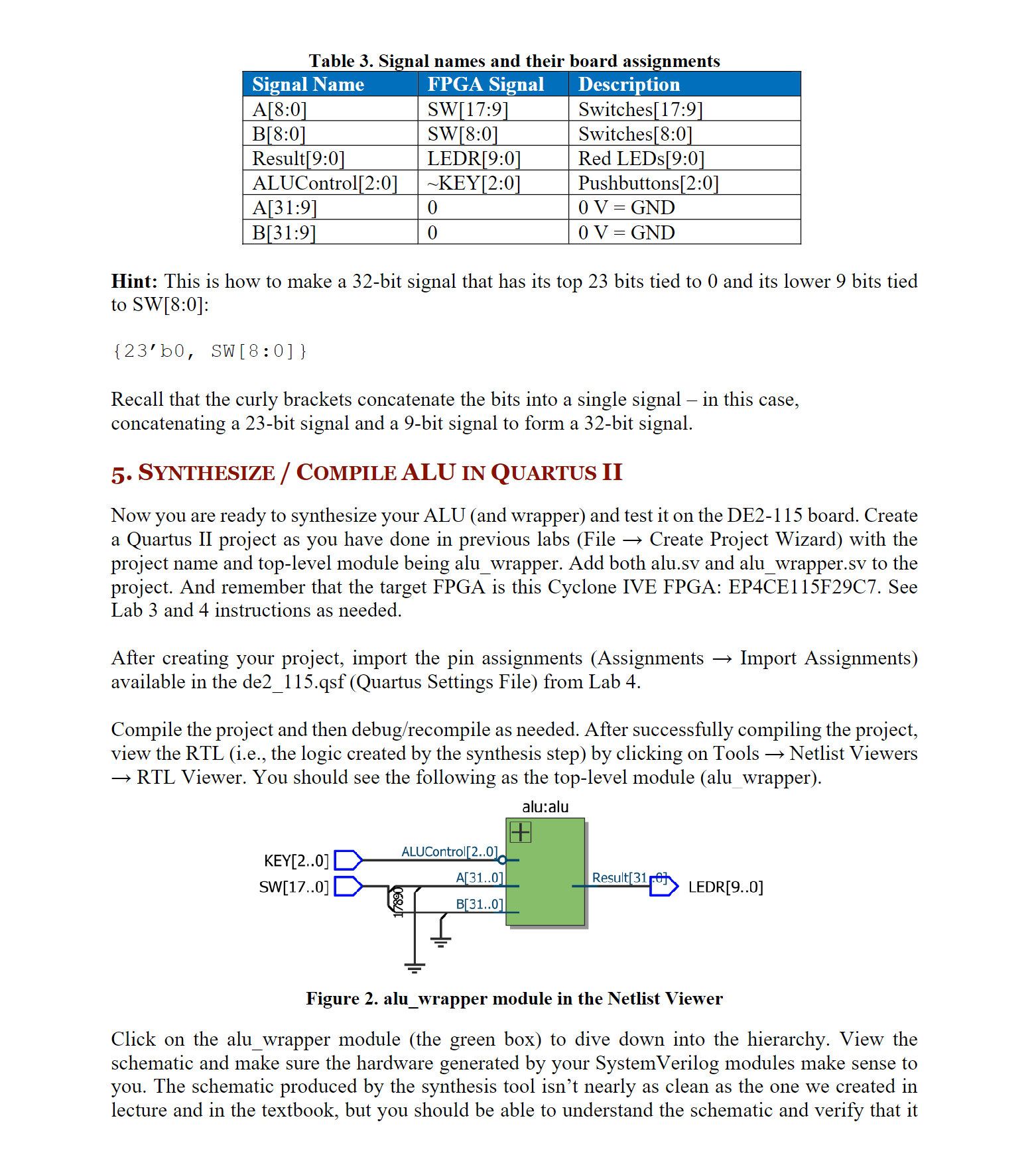
CREATE A WRAPPER MODULE FOR YOUR ALU
In order to build and test your bit ALU from Lab on the DE board, you will need to
map the interface to the board. You will do this by writing a wrapper file for your alu module. The
board has a limited number of switches, so you will only map the least significant bits of A and
to the switches and the least significant bits of Result to the red LEDs. The control input,
ALUControl, will map to the three rightmost pushbuttons. The pushbuttons are when pressed
and when not pressed, so ALUControl: is mapped to :; so the respective
ALUControl input will now be when pressed and when not pressed Write a wrapper file that
maps the interfaces as shown
Step by Step Solution
There are 3 Steps involved in it
1 Expert Approved Answer
Step: 1 Unlock

Question Has Been Solved by an Expert!
Get step-by-step solutions from verified subject matter experts
Step: 2 Unlock
Step: 3 Unlock