

Question: b ) ( 6 p ) The logic circuit shown below is a counter. Let's assume the clock signal is connected to a 2 4
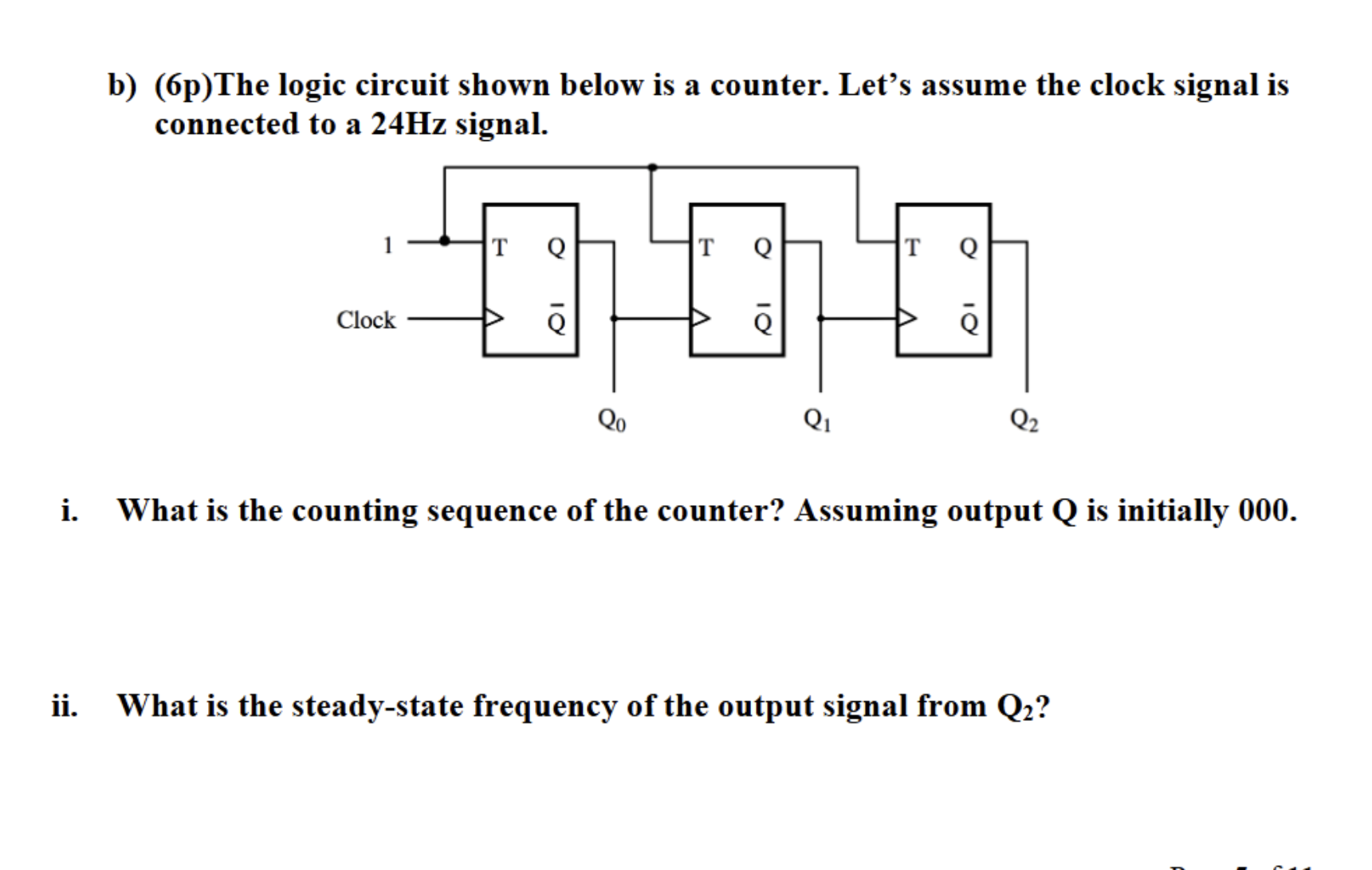
bpThe logic circuit shown below is a counter. Let's assume the clock signal is connected to a Hz signal.
i What is the counting sequence of the counter? Assuming output Q is initially
ii What is the steadystate frequency of the output signal from Q
Step by Step Solution
There are 3 Steps involved in it
1 Expert Approved Answer
Step: 1 Unlock

Question Has Been Solved by an Expert!
Get step-by-step solutions from verified subject matter experts
Step: 2 Unlock
Step: 3 Unlock