

Question: B a T 12 Link 2 02 A Link 3 60 Link 4 b 03 Fp 40F Bo W AA=, AB=b, BoB=c Vertical distance
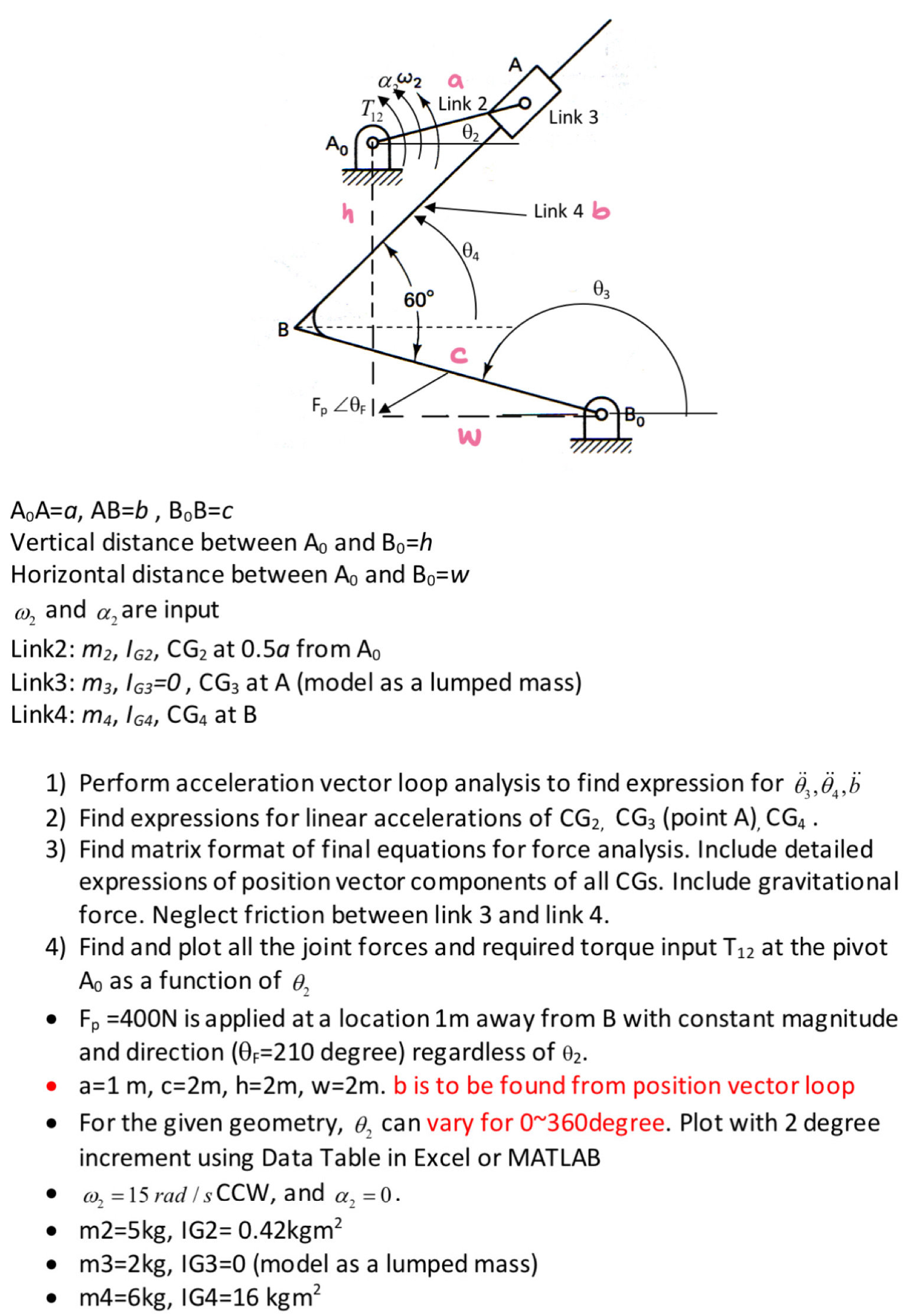
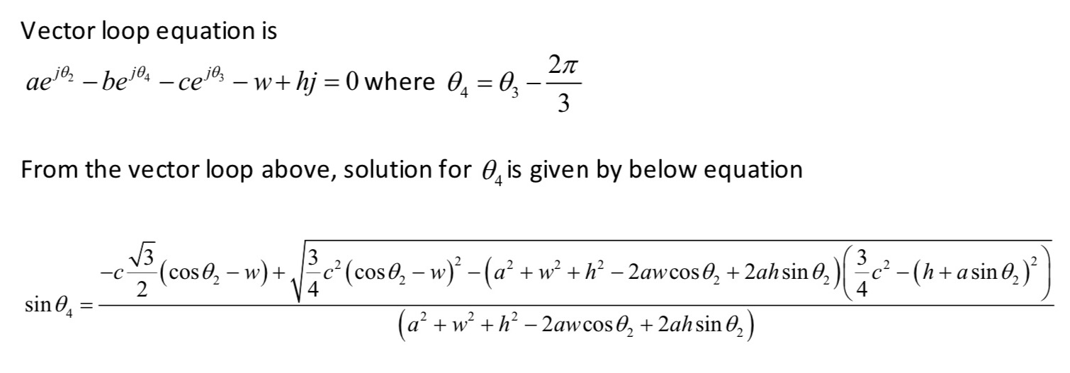
B a T 12 Link 2 02 A Link 3 60 Link 4 b 03 Fp 40F Bo W AA=, AB=b, BoB=c Vertical distance between A and Bo=h Horizontal distance between Ao and Bo=W and W2 a, are input Link2: m2, IG2, CG2 at 0.5a from Ao Link3: m3, IG3=0, CG3 at A (model as a lumped mass) Link4: m4, IG4, CG4 at B 1) Perform acceleration vector loop analysis to find expression for 2) Find expressions for linear accelerations of CG2, CG3 (point A), CG4. 3) Find matrix format of final equations for force analysis. Include detailed expressions of position vector components of all CGs. Include gravitational force. Neglect friction between link 3 and link 4. 4) Find and plot all the joint forces and required torque input T2 at the pivot A as a function of Fp =400N is applied at a location 1m away from B with constant magnitude and direction (0 =210 degree) regardless of 02. a=1 m, c=2m, h=2m, w=2m. b is to be found from position vector loop For the given geometry, 2 can vary for 0~360 degree. Plot with 2 degree increment using Data Table in Excel or MATLAB w = 15 rad/s CCW, and , = 0. m2=5kg, IG2= 0.42kgm m3=2kg, IG3=0 (model as a lumped mass) m4=6kg, IG4=16 kgm Vector loop equation is ae-be-ce3 w+hj = 0 where 0 = 03 2 3 From the vector loop above, solution for is given by below equation -c (coso - w) + c (coso - w) (a + w + h 2awcos + 2ahsin 0) - sin (a + w + h - 2awcos 02 + 2ah sin 02) 3 2 c - (h+asin 0)
Step by Step Solution
There are 3 Steps involved in it

Get step-by-step solutions from verified subject matter experts