

Question: (b) Construct the circuit for the state diagram shown in Figure Q1 using digital logic gates and D-Flip Flops. 01 1/0 1/0 0/0 00
![[Q3] (a) Briefly explain each phase of digital testing in a VLSI design flow using an illustration. (b)](https://dsd5zvtm8ll6.cloudfront.net/questions/2024/01/659e96bedb7f1_1704982048938.jpg)
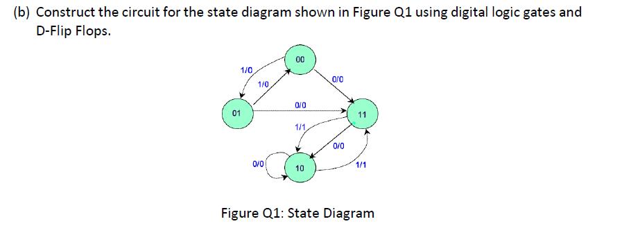
(b) Construct the circuit for the state diagram shown in Figure Q1 using digital logic gates and D-Flip Flops. 01 1/0 1/0 0/0 00 0/0 1/1 10 0/0 0/0 1/1 Figure Q1: State Diagram [Q3] (a) Briefly explain each phase of digital testing in a VLSI design flow using an illustration. (b) Briefly explain functional and structural testing with the fault model by considering the above circuit diagram Q1. (b).
Step by Step Solution
There are 3 Steps involved in it
To construct the circuit for the state diagram shown in the provided image using digital logic gates and DFlip Flops you need to follow several steps 1 Determine the states and state transitions From ... View full answer

Get step-by-step solutions from verified subject matter experts