

Question: b. d. - Geeks We want to design a mobile robot which has the following components: a. The robot has two DC motors actuating the
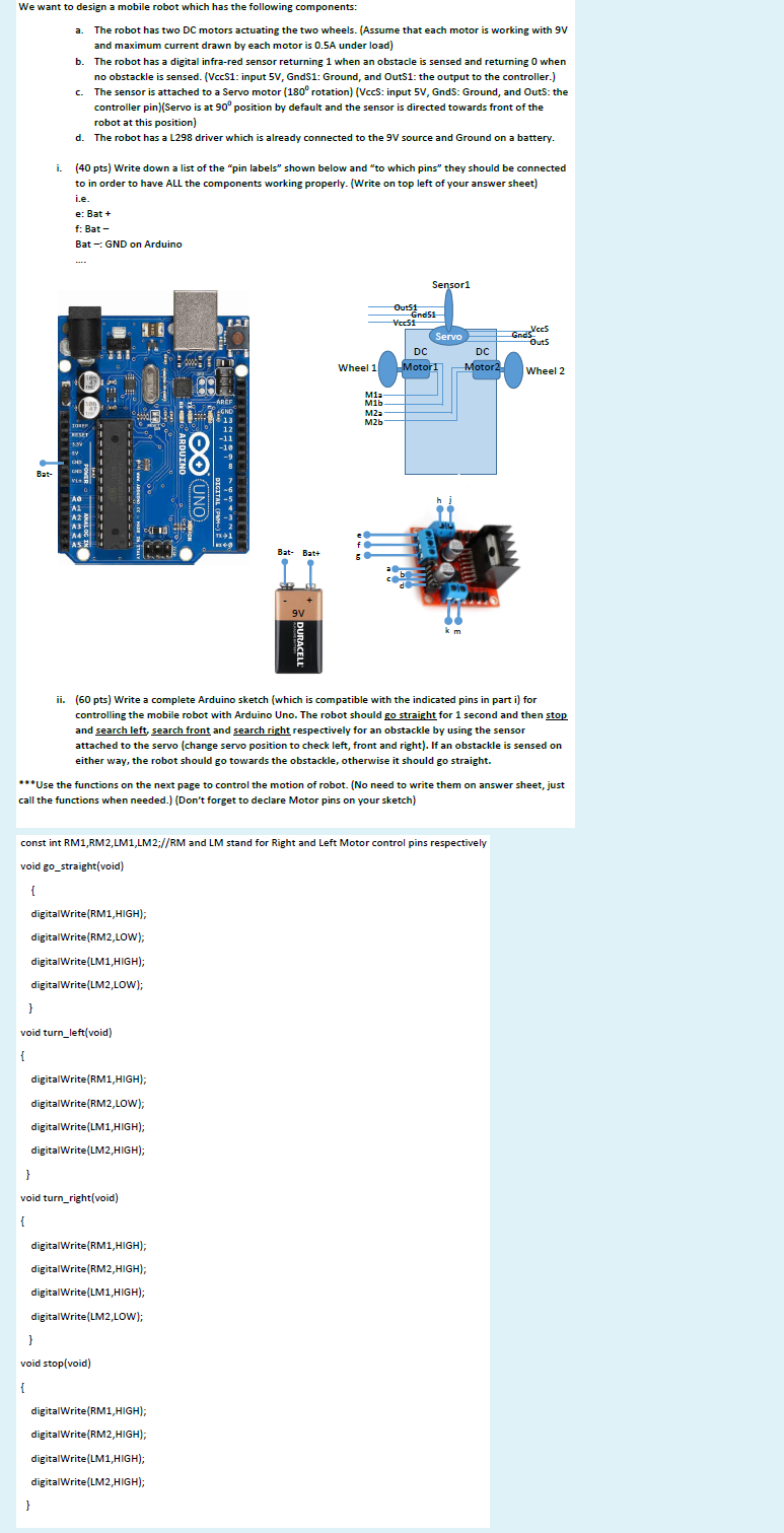
b. d. - Geeks We want to design a mobile robot which has the following components: a. The robot has two DC motors actuating the two wheels. (Assume that each motor is working with 9V and maximum current drawn by each motor is 0.5A under load) The robot has a digital infra-red sensor returning 1 when an obstacle is sensed and returning o when no obstackle is sensed. (VecS1: input 5V, GndS1: Ground, and Outs1: the output to the controller.) The sensor is attached to a Servo motor (180 rotation) (Vccs: input 5V, Gnds: Ground, and Outs: the controller pin)(Servo is at 90 position by default and the sensor is directed towards front of the robot at this position) The robot has a L298 driver which is already connected to the 9V source and Ground on a battery. i. (40 pts) Write down a list of the "pin labels" shown below and "to which pins" they should be connected to in order to have ALL the components working properly. (Write on top left of your answer sheet) i.e. e: Bat+ f: Bat- Bat - GND on Arduino Sensori -OutStress Veest Vecs Servo Outs DC DC Wheel 1 Motor 2 Wheel 2 Motor 1 AREF GND Mia 16. M2a M2b TORE RESET V HD ARDUINO Bat- VI DICITAL AO 11 Bat- Batt a 9V ii. (60 pts) Write a complete Arduino sketch (which is compatible with the indicated pins in part i) for ( controlling the mobile robot with Arduino Uno. The robot should go straight for 1 second and then stop and search left search front and search right respectively for an obstackle by using the sensor attached to the servo (change servo position to check left, front and right). If an obstackle is sensed on either way, the robot should go towards the obstackle, otherwise it should go straight. ***Use the functions on the next page to control the motion of robot. (No need to write them on answer sheet, just call the functions when needed.) (Don't forget to declare Motor pins on your sketch) const int RM1,RM2,LM1,LM2;//RM and LM stand for Right and Left Motor control pins respectively : void go_straight(void) { digitalWrite(RM1,HIGH); digitalWrite(RM2,LOW); digitalWrite(LM1, HIGH); digitalWrite(LM2,LOW); } void turn_left(void) { digitalWrite(RM1, HIGH); digitalWrite(RM2,LOW); digitalWrite(LM1, HIGH); digitalWrite(LM2, HIGH); } void turn_right(void) { digitalWrite(RM1, HIGH); digitalWrite(RM2, HIGH); digitalWrite(LM1, HIGH); digitalWrite(LM2,LOW); } void stop(void) 1 { digitalWrite(RM1, HIGH); digitalWrite(RM2, HIGH); digitalWrite(LM1, HIGH); digitalWrite(LM2,HIGH); }
Step by Step Solution
There are 3 Steps involved in it

Get step-by-step solutions from verified subject matter experts