

Question: b . In our simple digital voltmeter, the outputs from the encoder will drive one of the segments of the 7 - segment display. In
b In our simple digital voltmeter, the outputs from the encoder will drive one of the segments of the segment display. In Figure the e segment is not illuminated by a logic and is illuminated by a logic
Note the inverting inputs of the two input AND gates. The 'e'segment is illuminated for displaying the digits and while it is not illuminated for digits and The bottom AND gate outputs logic when none of the comparator outputs are logic V ie when Vin is V The top AND gate outputs logic when the outputs for comparators C and C are V logic and the outputs for comparators C C and C are V logic or logic when inverted
Using only inverters, input AND gates and a input OR gate in a similar way to Figure give a circuit diagram that will illuminate the a segment of the segment display for the corresponding digits between and You may use inverting inputs as illustrated by the small circles on the AND gate inputs in Figure Note that MultiSim Live does not use inverting inputs of logic gates.
marks
c Looking again at Figure one can see that the two input AND gates used to illuminate the e segment share equal values for some of the inputs, namely at inputs C C and C This means that the e segment is illuminated when C AND C AND C or in a compact form e CCC implemented as one input AND gate with inverters at its inputs for the signals C C and C This gives an idea how to reduce the number of gates and inputs for the decoder. Using this approach, give a similar implementation with a reduced number of gates and inputs for the decoder for the a segment. You may find it easier to use a truth table andor Karnaugh map in this part. Comment how this compares to the straightforward approach from Figure
marks
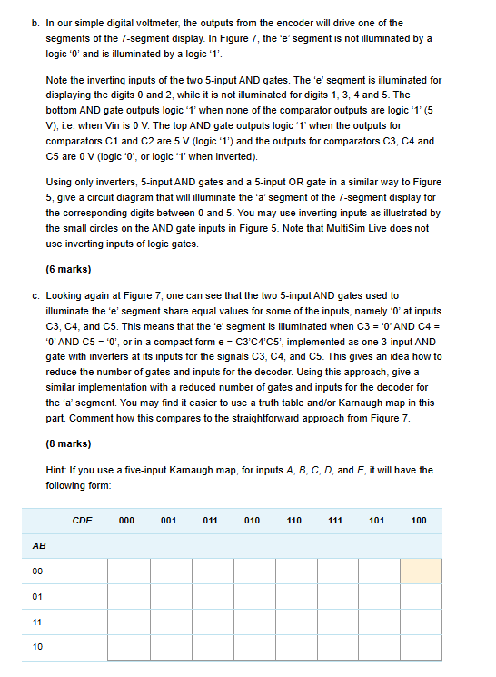
Hint: If you use a fiveinput Kamaugh map, for inputs A B C D and E it will have the following form:
Step by Step Solution
There are 3 Steps involved in it
1 Expert Approved Answer
Step: 1 Unlock

Question Has Been Solved by an Expert!
Get step-by-step solutions from verified subject matter experts
Step: 2 Unlock
Step: 3 Unlock