

Question: Based on the IOT device below, provide conditions and inputs that will lead to a simple design logic circuit IOT Device : Fingerprint sensor to
Based on the IOT device below, provide conditions and inputs that will lead to a simple design logic circuit
IOT Device : Fingerprint sensor to enter house.
The logic circuit must not be too simple. Try adding more conditions like motion sensor to detect motion to make the logic circuit more complex
The last time I asked another Chegg Expert, they provided me with such a simple answer. So, can you please add more conditions?
The format of the answer can be followed with the images provided below
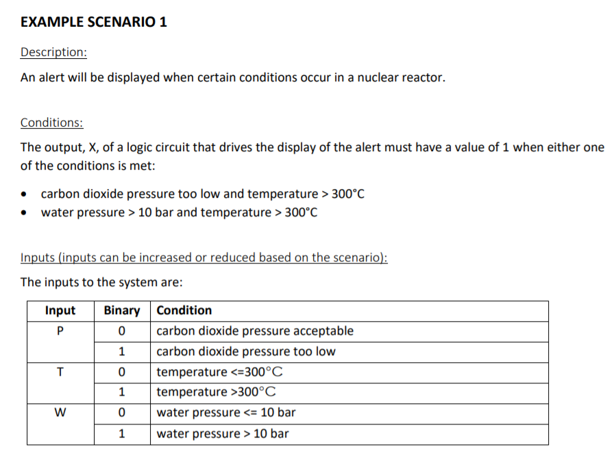
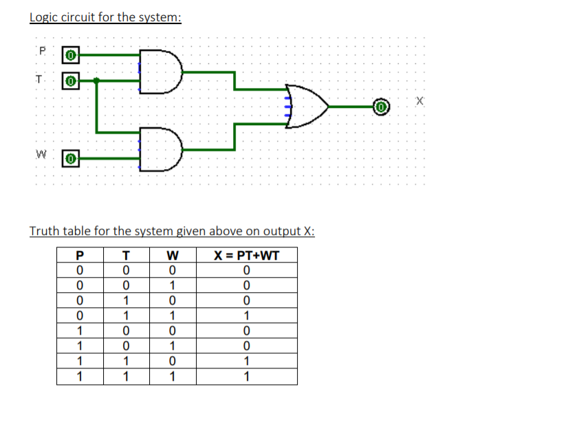
EXAMPLE SCENARIO 1 Description: An alert will be displayed when certain conditions occur in a nuclear reactor. Conditions: The output, X, of a logic circuit that drives the display of the alert must have a value of 1 when either one of the conditions is met: carbon dioxide pressure too low and temperature > 300C water pressure > 10 bar and temperature > 300C Inputs (inputs can be increased or reduced based on the scenario): The inputs to the system are: Input T Binary Condition 0 carbon dioxide pressure acceptable 1 carbon dioxide pressure too low 0 temperature 300C 0 water pressure 10 bar W Logic circuit for the system: 0 T 0 D X (0) 0 Truth table for the system given above on output X: P T W X = PT+WT 0 0 0 0 0 0 1 0 0 0 0 0 1 1 1 1 0 0 0 1 0 1 0 1 1 0 1 1 1 1 1 EXAMPLE SCENARIO 1 Description: An alert will be displayed when certain conditions occur in a nuclear reactor. Conditions: The output, X, of a logic circuit that drives the display of the alert must have a value of 1 when either one of the conditions is met: carbon dioxide pressure too low and temperature > 300C water pressure > 10 bar and temperature > 300C Inputs (inputs can be increased or reduced based on the scenario): The inputs to the system are: Input T Binary Condition 0 carbon dioxide pressure acceptable 1 carbon dioxide pressure too low 0 temperature 300C 0 water pressure 10 bar W Logic circuit for the system: 0 T 0 D X (0) 0 Truth table for the system given above on output X: P T W X = PT+WT 0 0 0 0 0 0 1 0 0 0 0 0 1 1 1 1 0 0 0 1 0 1 0 1 1 0 1 1 1 1 1
Step by Step Solution
There are 3 Steps involved in it

Get step-by-step solutions from verified subject matter experts