

Question: Logic gate question Below is the scenario given: Fingerprint sensor to enter house. (advanced home IOT device) Based on the scenario above, you are required
Logic gate question
Below is the scenario given:
Fingerprint sensor to enter house. (advanced home IOT device)
Based on the scenario above, you are required to come out with: 1. A description of each scenario. 2. Conditions for each scenario. 3. Inputs to the logic circuit (based on the conditions set on 2). 4. Design the logic circuits based on identified scenario. 5. Produce the truth table for identified scenario. You can use any logic circuit simulator to create the logic circuits, such as Logisim 2.7 for windows.
(The design must be must be a little complex, not just a simple input output such as turning on and off the light. The design needs more conditions and functions.)
(Description must also be descript in detailed along with the conditions as well)
Draw the logic circuit and implement different types of logic gate.
Refer to the example/format given below :
ADDITIONAL INFORMATION:
Scenario: Fingerprint sensor to enter house. (advanced home IOT device)
Functional Requirements: Design logic circuits using logic gates for the given scenario above based on the use of IoT devices typically found in a Smart Home environment.
Deliverables: For the given scenario, your are required to come out with: 1. A description of the scenario. 2. Conditions for the scenario. 3. Inputs to the logic circuit (based on the conditions set on 2). 4. Design the logic circuits based on identified scenario. 5. Produce the truth table for identified scenario. You can use any logic circuit simulator to create the logic circuits, such as Logisim 2.7 for windows.
Follow the format of the given example below to guide you on this question
You can also add additional functions to the scenario given
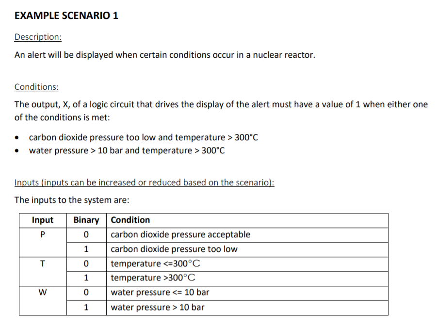
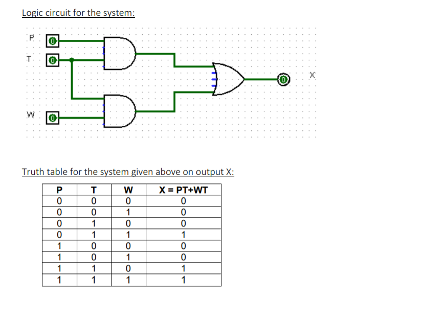
EXAMPLE SCENARIO 1 Description: An alert will be displayed when certain conditions occur in a nuclear reactor. Conditions: The output, X, of a logic circuit that drives the display of the alert must have a value of 1 when either one of the conditions is met: carbon dioxide pressure too low and temperature > 300C water pressure > 10 bar and temperature > 300C Inputs (inputs can be increased or reduced based on the scenario): The inputs to the system are: Input T Binary Condition 0 carbon dioxide pressure acceptable 1 carbon dioxide pressure too low 0 temperature 300C 0 water pressure 10 bar W Logic circuit for the system: 0 T 0 D X (0) 0 Truth table for the system given above on output X: P T W X = PT+WT 0 0 0 0 0 0 1 0 0 0 0 0 1 1 1 1 0 0 0 1 0 1 0 1 1 0 1 1 1 1 1 EXAMPLE SCENARIO 1 Description: An alert will be displayed when certain conditions occur in a nuclear reactor. Conditions: The output, X, of a logic circuit that drives the display of the alert must have a value of 1 when either one of the conditions is met: carbon dioxide pressure too low and temperature > 300C water pressure > 10 bar and temperature > 300C Inputs (inputs can be increased or reduced based on the scenario): The inputs to the system are: Input T Binary Condition 0 carbon dioxide pressure acceptable 1 carbon dioxide pressure too low 0 temperature 300C 0 water pressure 10 bar W Logic circuit for the system: 0 T 0 D X (0) 0 Truth table for the system given above on output X: P T W X = PT+WT 0 0 0 0 0 0 1 0 0 0 0 0 1 1 1 1 0 0 0 1 0 1 0 1 1 0 1 1 1 1 1
Step by Step Solution
There are 3 Steps involved in it

Get step-by-step solutions from verified subject matter experts