

Question: begin { tabular } { | c | c | c | c | c | c | c | c | c |
begintabularccccccccccc
hline multicolumncArea cm & multicolumncCoordinates m & Rad & Grade
hline A & A & A & x & X & X & Y & Y & Y & &
hline & & & & & & & & & & S
hline
endtabular
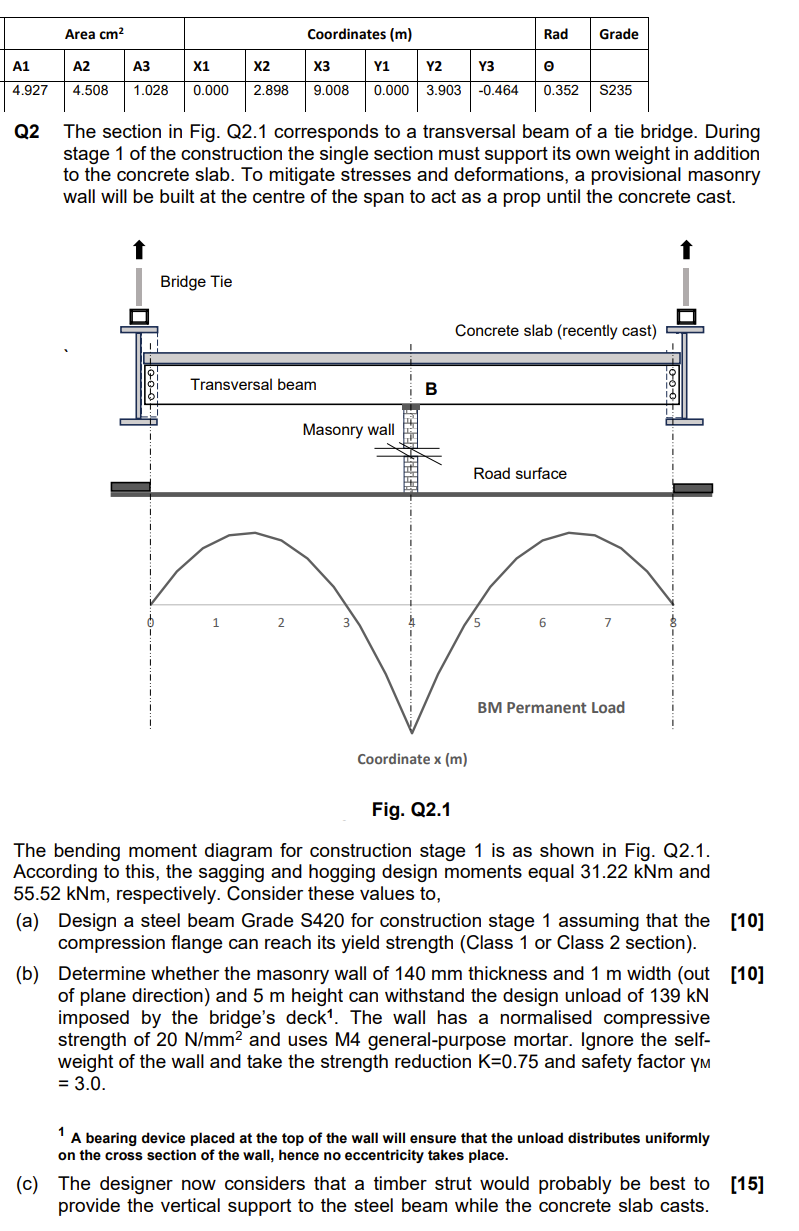
Q The section in Fig. Q corresponds to a transversal beam of a tie bridge. During stage of the construction the single section must support its own weight in addition to the concrete slab. To mitigate stresses and deformations, a provisional masonry wall will be built at the centre of the span to act as a prop until the concrete cast.
rig. WL I
The bending moment diagram for construction stage is as shown in Fig. Q According to this, the sagging and hogging design moments equal kNm and kNm respectively. Consider these values to
a Design a steel beam Grade S for construction stage assuming that the compression flange can reach its yield strength Class or Class section
b Determine whether the masonry wall of mm thickness and m width out
of plane direction and m height can withstand the design unload of kN imposed by the bridge's deck The wall has a normalised compressive strength of mathrm~Nmathrmmm and uses M generalpurpose mortar. Ignore the selfweight of the wall and take the strength reduction mathrmK and safety factor mathrmym
A bearing device placed at the top of the wall will ensure that the unload distributes uniformly on the cross section of the wall, hence no eccentricity takes place.
c The designer now considers that a timber strut would probably be best to
provide the vertical support to the steel beam while the concrete slab casts.
Step by Step Solution
There are 3 Steps involved in it
1 Expert Approved Answer
Step: 1 Unlock

Question Has Been Solved by an Expert!
Get step-by-step solutions from verified subject matter experts
Step: 2 Unlock
Step: 3 Unlock