

Question: begin { tabular } { | l | l | l | } hline & begin { tabular } { l }
begintabularlll
hline & begintabularl
Islamic University of Gaza
Department of Electrical Engineering
EELE EELE
Hw#Fall
endtabular & NAME:
hline
endtabular
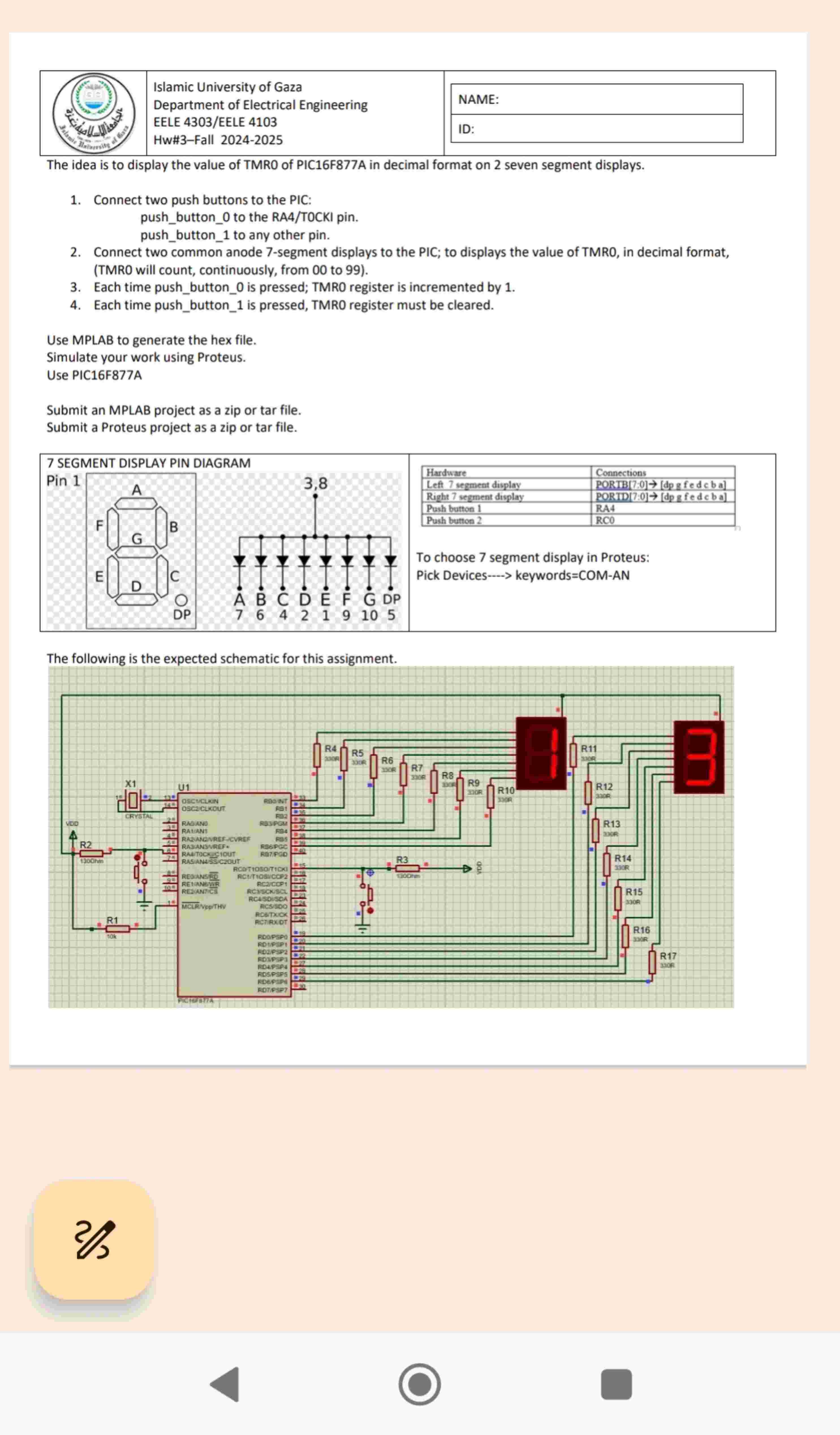
The idea is to display the value of TMR of PICFA in decimal format on seven segment displays.
Connect two push buttons to the PIC: pushbutton to the RATOCKI pin. pushbutton to any other pin.
Connect two common anode segment displays to the PIC; to displays the value of TMRO, in decimal format, TMRO will count, continuously, from to
Each time pushbutton is pressed; TMRO register is incremented by
Each time pushbutton is pressed, TMRO register must be cleared.
Use MPLAB to generate the hex file.
Simulate your work using Proteus.
Use PICFA
Submit an MPLAB project as a zip or tar file.
Submit a Proteus project as a zip or tar file.
begintabularll
hline Hardware & Connections
hline Left segment display & PORTB : rightarrowmathrmdpg fed c b a
hline Right segment display & PORTD : rightarrowmathrmdpmathrmfedcba
hline Push button & RA
hline Push button & RC
hline
endtabular
To choose segment display in Proteus:
Pick Devices keywordsCOMAN
The following is the expected schematic for this assignment.
Step by Step Solution
There are 3 Steps involved in it
1 Expert Approved Answer
Step: 1 Unlock

Question Has Been Solved by an Expert!
Get step-by-step solutions from verified subject matter experts
Step: 2 Unlock
Step: 3 Unlock