

Question: Below is a circuit diagram for a bidirectional shift register using D flip - flops. ( i ) Is this a Mealy Machine or a
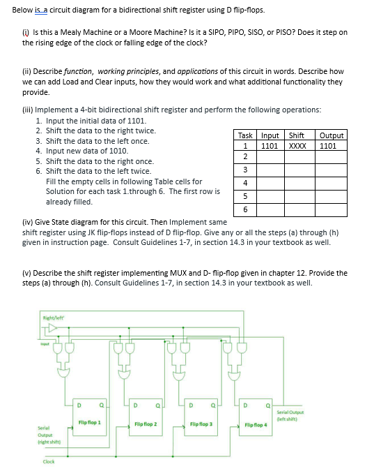
Below is a circuit diagram for a bidirectional shift register using D flipflops.
i Is this a Mealy Machine or a Moore Machine? Is it a SIPO, PIPO, SISO, or PISO? Does it step on the rising edge of the clock or falling edge of the clock?
ii Describe function, working principles, and applications of this circuit in words. Describe how we can add Load and Clear inputs, how they would work and what additional functionality they provide.
iii Implement a bit bidirectional shift register and perform the following operations:
Input the initial data of
Shift the data to the right twice.
Shift the data to the left once.
Input new data of
Shift the data to the right once.
Shift the data to the left twice.
Fill the empty cells in following Table cells for Solution for each task through The first row is already filled.
iv Give State diagram for this circuit. Then Implement same
begintabularclll
hline Task & Input & Shift & Output
hline & & XXXX &
hline & & &
hline & & &
hline & & &
hline & & &
hline & & &
hline
endtabular
shift register using JK flipflops instead of D flipflop. Give any or all the steps a through h given in instruction page. Consult Guidelines in section in your textbook as well.
v Describe the shift register implementing MUX and Dflipflop given in chapter Provide the steps a through h Consult Guidelines in section in your textbook as well.
Step by Step Solution
There are 3 Steps involved in it
1 Expert Approved Answer
Step: 1 Unlock

Question Has Been Solved by an Expert!
Get step-by-step solutions from verified subject matter experts
Step: 2 Unlock
Step: 3 Unlock