

Question: Below schematic represents a given circuit which has two 4-bits inputs IN0 and IN1,1-bit input IN2, and one 5-bits output F. This circuit has to
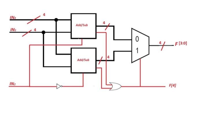
Below schematic represents a given circuit which has two 4-bits inputs IN0 and IN1,1-bit input IN2, and one 5-bits output F.
This circuit has to calculate IN0 + IN1 and IN0 IN1, the output result depends on the values of the overflow bits in both add/sub units.
1. Write Verilog structural code for this circuit
2. Write Verilog test bench for this circuit, use at least four different set of input stimulus
Step by Step Solution
There are 3 Steps involved in it
1 Expert Approved Answer
Step: 1 Unlock

Question Has Been Solved by an Expert!
Get step-by-step solutions from verified subject matter experts
Step: 2 Unlock
Step: 3 Unlock