

Question: BUILD LOGIC CIRCUITS UNDER THESE QUESTIONS. ANY HELP WILL BE APPRECIATED! 1. In Logisim, Build a 1-bit adder from AND, OR, and NOT gates. The
BUILD LOGIC CIRCUITS UNDER THESE QUESTIONS. ANY HELP WILL BE APPRECIATED!
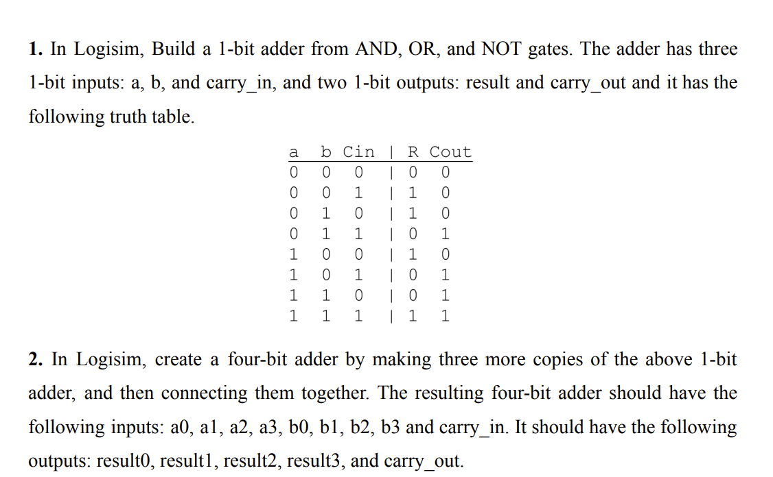
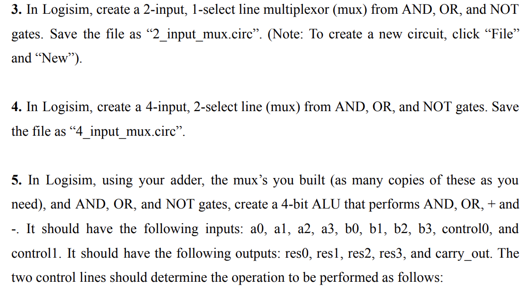
1. In Logisim, Build a 1-bit adder from AND, OR, and NOT gates. The adder has three 1-bit inputs: a, b, and carry_in, and two 1-bit outputs: result and carry_out and it has the following truth table. 2. In Logisim, create a four-bit adder by making three more copies of the above 1-bit adder, and then connecting them together. The resulting four-bit adder should have the following inputs: a0, a1, a2, a3, b0, b1, b2, b3 and carry_in. It should have the following outputs: result 0 , result 1 , result 2 , result 3 , and carry_out. 3. In Logisim, create a 2-input, 1-select line multiplexor (mux) from AND, OR, and NOT gates. Save the file as "2_input_mux.circ". (Note: To create a new circuit, click "File" and "New"). 4. In Logisim, create a 4-input, 2-select line (mux) from AND, OR, and NOT gates. Save the file as "4_input_mux.circ". 5. In Logisim, using your adder, the mux's you built (as many copies of these as you need), and AND, OR, and NOT gates, create a 4-bit ALU that performs AND, OR, + and -. It should have the following inputs: a0, a1, a2, a3, b0, b1, b2, b3, control0, and control1. It should have the following outputs: res0, res1, res2, res3, and carry_out. The two control lines should determine the operation to be performed as follows
Step by Step Solution
There are 3 Steps involved in it

Get step-by-step solutions from verified subject matter experts