

Question: Build the circuit from Part I step 2 in Multisim. Use the interactive switch SPST shown in step 1 to replace the pushbutton. Carry out
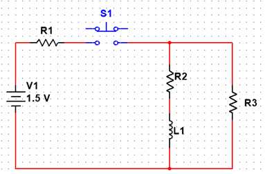
- Build the circuit from Part I step 2 in Multisim. Use the interactive switch SPST shown in step 1 to replace the pushbutton. Carry out the following scenario: (1) Begin with switch S1 open, (2) close switch S1 long enough till the voltage across the inductor is almost zero, and then (3) open switch S1 for a long time beginning at time t = 0. Connect the oscilloscope to monitor the voltage v (t) across R3. Run interactive simulation, adjusting the oscilloscope settings to make the waveform fill a reasonable amount of the available display in both the vertical and horizontal directions. Include the screenshot of your waveform in your lab report. Use edge triggering and the Normal triggering mode to capture the transient when the switch opens. If needed, you can decrease the time step size of interactive simulation to achieve higher resolution; Use the oscilloscope cursor to measure the magnitude of the peak value of v (t).
- R1 = 10 , R2 = 100, R3 = 470, L1 = 33mH
- ,
$1. R1 R2 V1 21.5 V R3 L1 $1. R1 R2 V1 21.5 V R3 L1
Step by Step Solution
There are 3 Steps involved in it
1 Expert Approved Answer
Step: 1 Unlock

Question Has Been Solved by an Expert!
Get step-by-step solutions from verified subject matter experts
Step: 2 Unlock
Step: 3 Unlock