

Question: Consider the op amp integrator circuit in Fig. 4. a) Set up the op amp integrator circuit as shown in Fig. 4. Give a
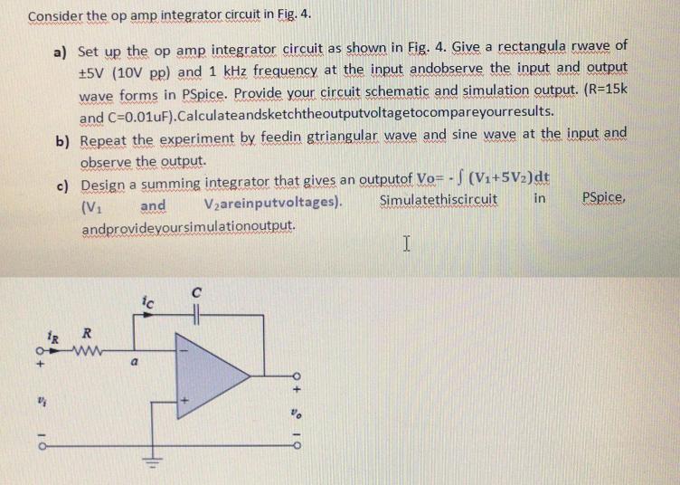
Consider the op amp integrator circuit in Fig. 4. a) Set up the op amp integrator circuit as shown in Fig. 4. Give a rectangula rwave of +5V (10V pp) and 1 kHz frequency at the input andobserve the input and output wave forms in PSpice. Provide your circuit schematic and simulation output. (R=15k and C=0.01uF).Calculateandsketchtheoutputvoltagetocompareyourresults. b) Repeat the experiment by feedin gtriangular wave and sine wave at the input and observe the output. c) Design a summing integrator that gives an outputof Vo= - S (V1+5V2)dt V2areinputvoltages). (V1 and Simulatethiscircuit in PSpice, andprovideyoursimulationoutput. C ic R a.
Step by Step Solution
3.31 Rating (151 Votes )
There are 3 Steps involved in it
a Op amp integrator output wave ... View full answer

Get step-by-step solutions from verified subject matter experts