Question: C. The network pictured below represents the layout of computers in a wired office layout. All possible wiring paths are shown. (Some obstacles exist between
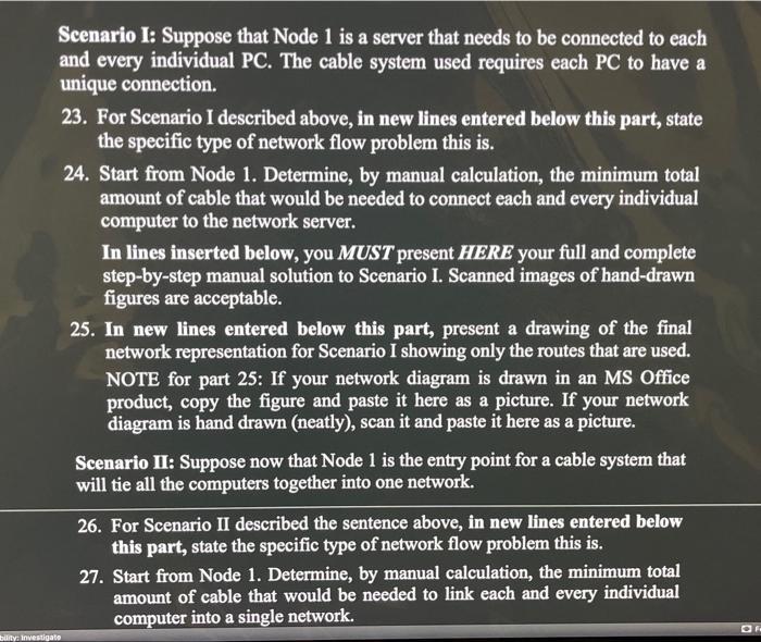
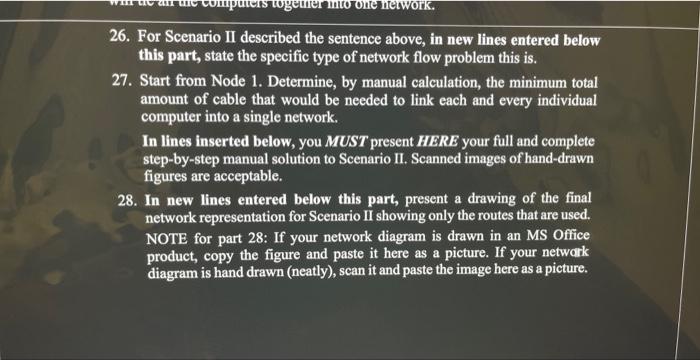
C. The network pictured below represents the layout of computers in a wired office layout. All possible wiring paths are shown. (Some obstacles exist between computers that eliminate some possible paths.) Each node is a location of a PC and the branches represent cables connecting the computers. The number on a branch indicates the length of the path in meters. (NOTE: The figure is not drawn to scale.) Scenario I: Suppose that Node 1 is a server that needs to be connected to each and every individual PC. The cable system used requires each PC to have a unique connection. 23. For Scenario I described above, in new lines entered below this part, state the specific type of network flow problem this is. 24. Start from Node 1. Determine, by manual calculation, the minimum total amount of cable that would be needed to connect each and every individual computer to the network server. In lines inserted below, you MUST present HERE your full and complete step-by-step manual solution to Scenario I. Scanned images of hand-drawn figures are acceptable. 25. In new lines entered below this part, present a drawing of the final network representation for Scenario I showing only the routes that are used. NOTE for part 25: If your network diagram is drawn in an MS Office product, copy the figure and paste it here as a picture. If your network diagram is hand drawn (neatly), scan it and paste it here as a picture. Scenario II: Suppose now that Node 1 is the entry point for a cable system that will tie all the computers together into one network. 26. For Scenario II described the sentence above, in new lines entered below this part, state the specific type of network flow problem this is. 27. Start from Node 1. Determine, by manual calculation, the minimum total amount of cable that would be needed to link each and every individual computer into a single network. 26. For Scenario II described the sentence above, in new lines entered below this part, state the specific type of network flow problem this is. 27. Start from Node 1. Determine, by manual calculation, the minimum total amount of cable that would be needed to link each and every individual computer into a single network. In lines inserted below, you MUST present HERE your full and complete step-by-step manual solution to Scenario II. Scanned images of hand-drawn figures are acceptable. 28. In new lines entered below this part, present a drawing of the final network representation for Scenario II showing only the routes that are used. NOTE for part 28: If your network diagram is drawn in an MS Office product, copy the figure and paste it here as a picture. If your netwark diagram is hand drawn (neatly), scan it and paste the image here as a picture