

Question: . In new lines entered below this part, present a drawing of the final network representation showing only the routes that are used. C. The
. In new lines entered below this part, present a drawing of the final network representation showing only the routes that are used.
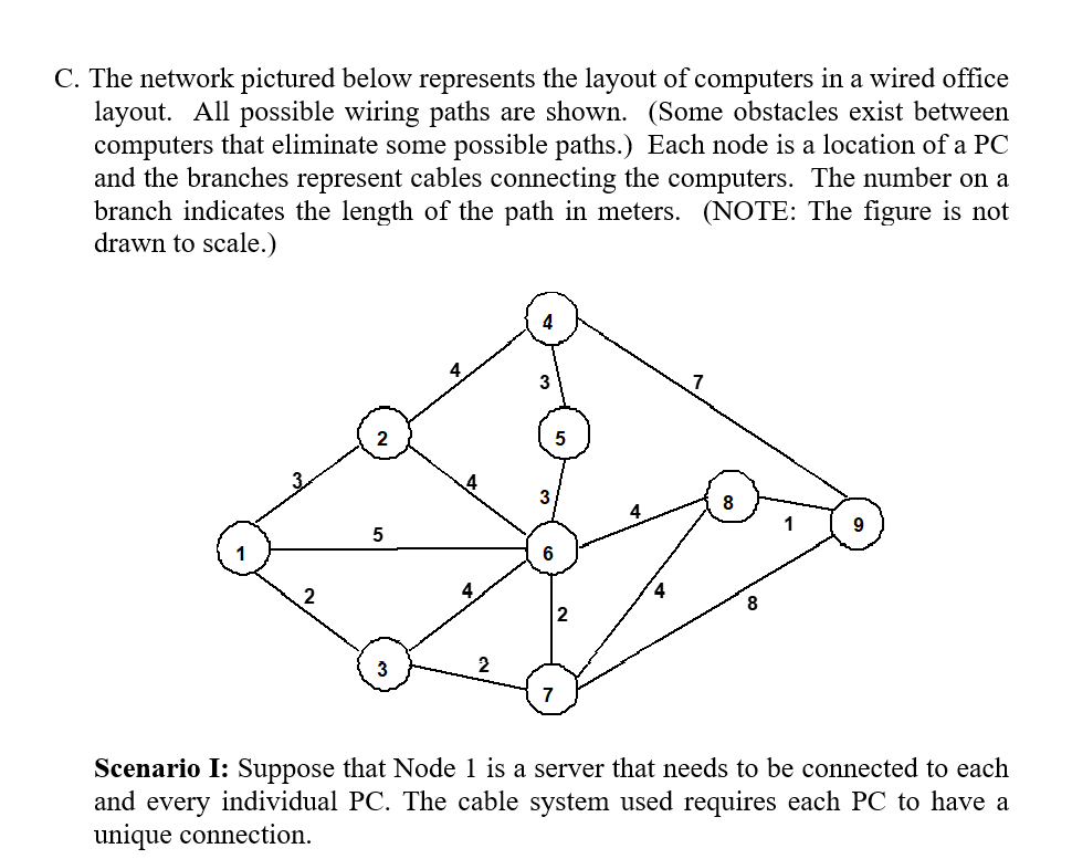
C. The network pictured below represents the layout of computers in a wired office layout. All possible wiring paths are shown. (Some obstacles exist between computers that eliminate some possible paths.) Each node is a location of a PC and the branches represent cables connecting the computers. The number on a branch indicates the length of the path in meters. (NOTE: The figure is not drawn to scale.) 4 4 5 8 5 1 4 8 2 7 Scenario I: Suppose that Node 1 is a server that needs to be connected to each and every individual PC. The cable system used requires each PC to have a unique connectionStep by Step Solution
There are 3 Steps involved in it
1 Expert Approved Answer
Step: 1 Unlock

Question Has Been Solved by an Expert!
Get step-by-step solutions from verified subject matter experts
Step: 2 Unlock
Step: 3 Unlock