

Question: can i get some help please never used Pspice before and very confused on it please Set up the diode circuit shown below on Schematics
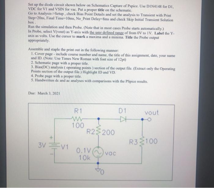
Set up the diode circuit shown below on Schematics Capture of Pspice. Use DIN4148 for DI, VDC for VI and VSIN for vac. Put a proper title on the schematic Go to Analysis->Setup. check Bias Point Details and set the analysis to Transient with Print Step-20ns, Final Time=10ms, No Print Delay-8ms and check Skip Initial Transient Solution box Run the simulation and then Probe. (Note that in most cases Probe starts automatically.) In Probe, select V[yout) as Y-axis with the user defined range of from 0 to 1V. Label the Y- axis as volts. Use the cursor to mark a maxima and a minima. Title the Probe output appropriately Assemble and staple the print out in the following manner: 1. Cover page - include course number and name, the title of this assignment, date, your name and ID. (Note: Use Times New Roman with font size of 12pt) 2. Schematic page with a proper title. 3. Bias(DC) analysis operating points ) section of the output file. (Extract only the Operating Points section of the output file.) Highlight ID and VD. 4. Probe page with a proper title. 5. Handwritten de and ac analyses with comparisons with the PSpice results. Due: March 3, 2021 R1 D1 DE vout 100 R23200 R3 $100 3V = V1 0.1V 1 OK vac
Step by Step Solution
There are 3 Steps involved in it

Get step-by-step solutions from verified subject matter experts