

Question: ch 8 - 9 * D 1 1 . 5 For the transistors in the circuit in Figure P 1 1 . 5 , the
ch
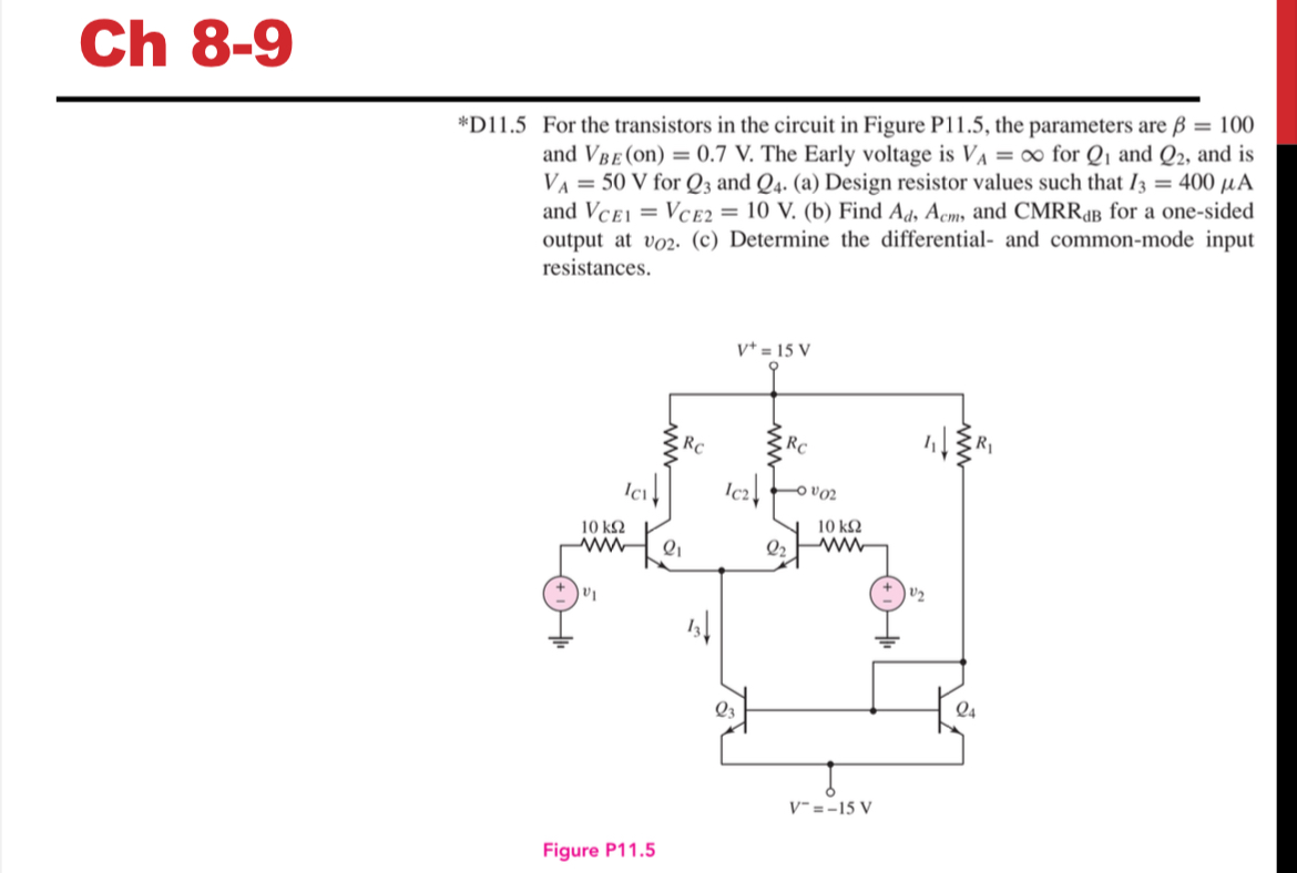
D For the transistors in the circuit in Figure P the parameters are and The Early voltage is for and and is for and a Design resistor values such that and b Find and for a onesided output at c Determine the differential and commonmode input resistances.
rigure r
Step by Step Solution
There are 3 Steps involved in it
1 Expert Approved Answer
Step: 1 Unlock

Question Has Been Solved by an Expert!
Get step-by-step solutions from verified subject matter experts
Step: 2 Unlock
Step: 3 Unlock