

Question: 1. With reference to the relay schematic diagram in Figure 7-37 (shown in next page), a. State the status of each light after each
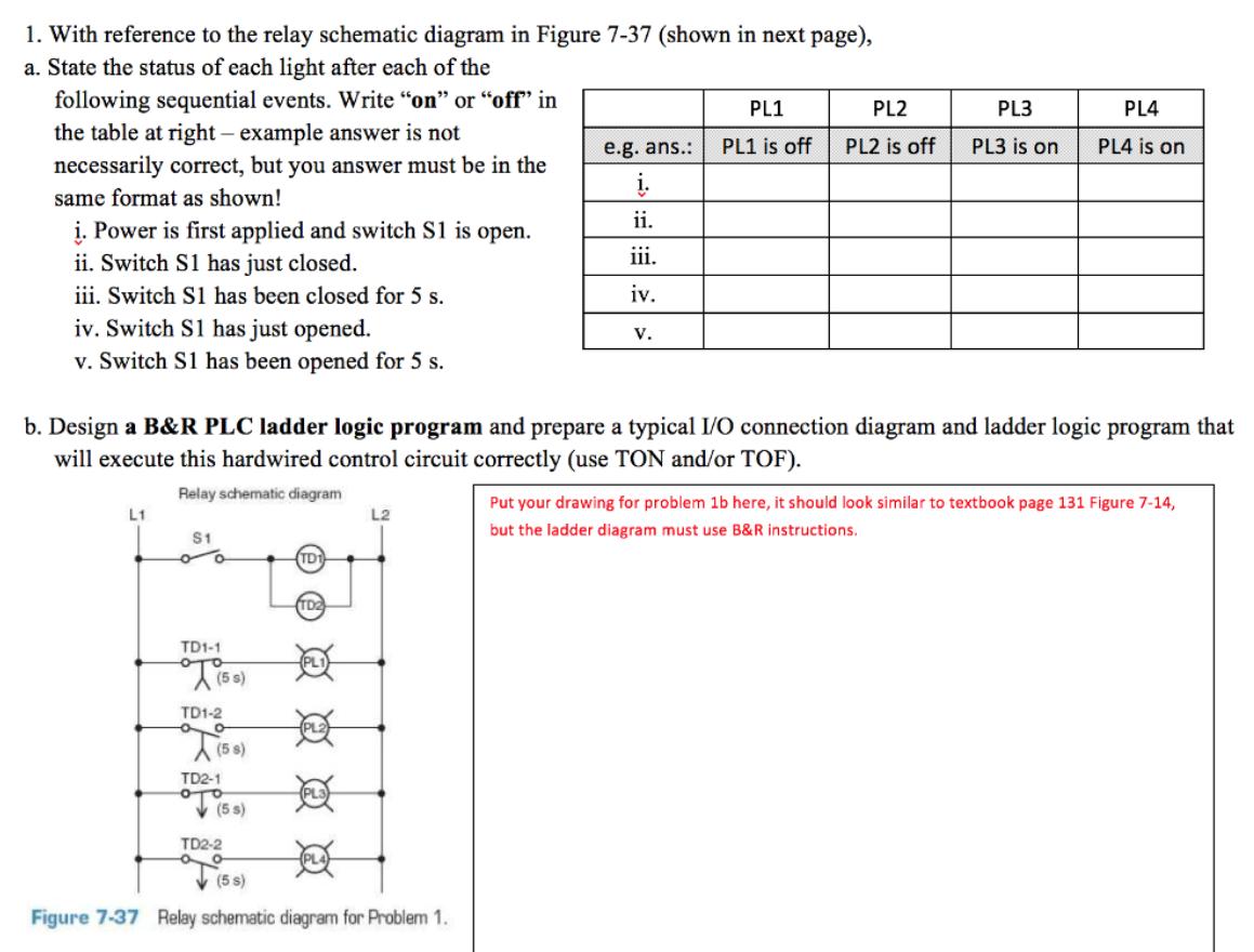
1. With reference to the relay schematic diagram in Figure 7-37 (shown in next page), a. State the status of each light after each of the following sequential events. Write "on" or "off in the table at right example answer is not PL1 PL2 PL3 PL4 e.g. ans.: PL1 is off PL2 is off PL3 is on PL4 is on necessarily correct, but you answer must be in the . same format as shown! ii. i. Power is first applied and switch S1 is open. ii. Switch S1 has just closed. iii. Switch S1 has been closed for 5 s. iv. Switch S1 has just opened. v. Switch S1 has been opened for 5 s. iii. iv. v. b. Design a B&R PLC ladder logic program and prepare a typical I/O connection diagram and ladder logic program that will execute this hardwired control circuit correctly (use TON and/or TOF). Relay schematic diagram Put your drawing for problem 1b here, it should look similar to textbook page 131 Figure 7-14, L1 L2 S1 but the ladder diagram must use B&R instructions. TD TD1-1 TD1-2 (5 s) TD2-1 (s 9) TD2-2 (5 s) Figure 7-37 Relay schematic diagram for Problem 1.
Step by Step Solution
3.53 Rating (156 Votes )
There are 3 Steps involved in it
1 a assuming both timers are TON i when power is applied and switch s1 is open then TD11NC contact w... View full answer

Get step-by-step solutions from verified subject matter experts