

Question: Circuit Design: You are required to use the LogicWork_5 program to conduct a 4-bit binary parallel subtractor as shown in the following figure. JE 0
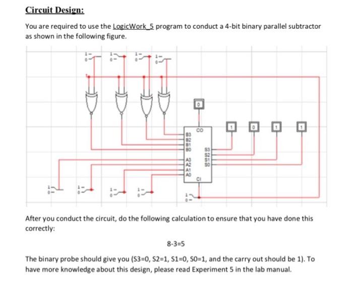
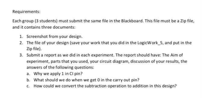
Circuit Design: You are required to use the LogicWork_5 program to conduct a 4-bit binary parallel subtractor as shown in the following figure. JE 0 CO 3858 2222 8388 $ AD CI After you conduct the circuit, do the following calculation to ensure that you have done this correctly: 8-3=5 The binary probe should give you (S3=0, S2=1, S1=0, So=1, and the carry out should be 1). To have more knowledge about this design, please read Experiment 5 in the lab manual. Requirements: Each group (3 students) must submit the same file in the Blackboard. This file must be a Zip file, and it contains three documents: 1. Screenshot from your design. 2. The file of your design (save your work that you did in the LogicWork_5, and put in the Zip file). 3. Submit a report as we did in each experiment. The report should have: The aim of experiment, parts that you used, your circuit diagram, discussion of your results, the answers of the following questions: a. Why we apply 1 in Cl pin? b. What should we do when we get in the carry out pin? C. How could we convert the subtraction operation to addition in this design
Step by Step Solution
There are 3 Steps involved in it

Get step-by-step solutions from verified subject matter experts