

Question: Complete the code please.. Dir: There are three ways the coils of a BLDC need to be driven 1) High side FET driven with PWM_sig
Complete the code please..
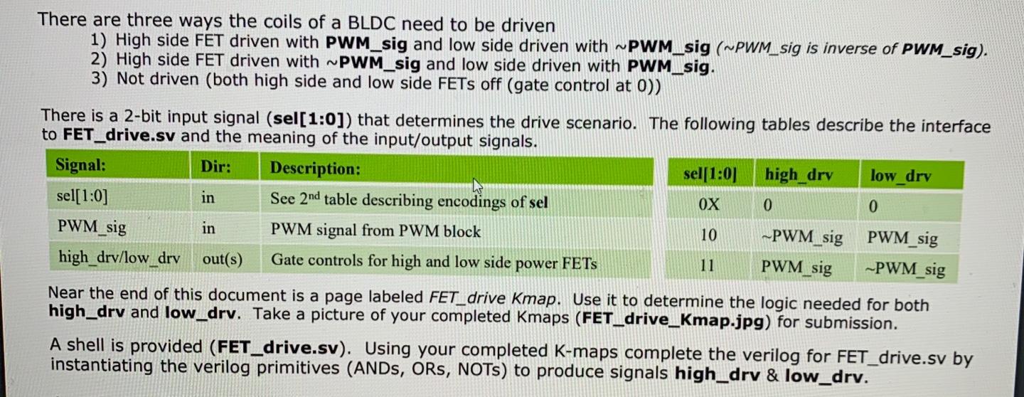
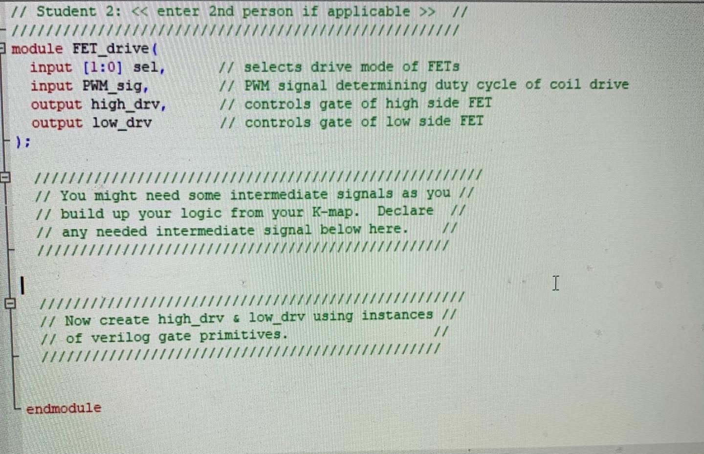
Dir: There are three ways the coils of a BLDC need to be driven 1) High side FET driven with PWM_sig and low side driven with ~PWM_sig (~PWM_sig is inverse of PWM_sig). 2) High side FET driven with ~PWM_sig and low side driven with PWM_sig. 3) Not driven (both high side and low side FETs off (gate control at 0)) There is a 2-bit input signal (sel[1:0]) that determines the drive scenario. The following tables describe the interface to FET_drive.sv and the meaning of the input/output signals. Signal: Description: sel(1:0) high_dry low_drv sel[1:0] in See 2nd table describing encodings of sel OX 0 0 PWM_sig in PWM signal from PWM block 10 ~PWM_sig PWM_sig high_drv/low_drv out(s) Gate controls for high and low side power FETs 11 PWM_sig PWM sig Near the end of this document is a page labeled FET_drive Kmap. Use it to determine the logic needed for both high_drv and low_drv. Take a picture of your completed Kmaps (FET_drive_Kmap.jpg) for submission. A shell is provided (FET_drive.sv). Using your completed K-maps complete the verilog for FET_drive.sv by instantiating the verilog primitives (ANDS, ORs, NOTs) to produce signals high_drv & low_drv. // Student 2: > // 3 module FET drive input [1:0] sel, input PWM_sig, output high_drv, output low_drv // selects drive mode of FETs // PWM signal determining duty cycle of coil drive // controls gate of high side FET // controls gate of low side FET ///// /// // You might need some intermediate signals as you // // build up your logic from your K-map. Declare // any needed intermediate signal below here. 1 I 11/ // Now create high_drv & low_drv using instances // // of verilog gate primitives. endmodule Dir: There are three ways the coils of a BLDC need to be driven 1) High side FET driven with PWM_sig and low side driven with ~PWM_sig (~PWM_sig is inverse of PWM_sig). 2) High side FET driven with ~PWM_sig and low side driven with PWM_sig. 3) Not driven (both high side and low side FETs off (gate control at 0)) There is a 2-bit input signal (sel[1:0]) that determines the drive scenario. The following tables describe the interface to FET_drive.sv and the meaning of the input/output signals. Signal: Description: sel(1:0) high_dry low_drv sel[1:0] in See 2nd table describing encodings of sel OX 0 0 PWM_sig in PWM signal from PWM block 10 ~PWM_sig PWM_sig high_drv/low_drv out(s) Gate controls for high and low side power FETs 11 PWM_sig PWM sig Near the end of this document is a page labeled FET_drive Kmap. Use it to determine the logic needed for both high_drv and low_drv. Take a picture of your completed Kmaps (FET_drive_Kmap.jpg) for submission. A shell is provided (FET_drive.sv). Using your completed K-maps complete the verilog for FET_drive.sv by instantiating the verilog primitives (ANDS, ORs, NOTs) to produce signals high_drv & low_drv. // Student 2: > // 3 module FET drive input [1:0] sel, input PWM_sig, output high_drv, output low_drv // selects drive mode of FETs // PWM signal determining duty cycle of coil drive // controls gate of high side FET // controls gate of low side FET ///// /// // You might need some intermediate signals as you // // build up your logic from your K-map. Declare // any needed intermediate signal below here. 1 I 11/ // Now create high_drv & low_drv using instances // // of verilog gate primitives. endmodule
Step by Step Solution
There are 3 Steps involved in it

Get step-by-step solutions from verified subject matter experts