

Question: Complete the tables 8.1 (a) and 8.1 (b)below: Build the following circuit. v Replace the 10 resistor with a multi-sim one-but if you are in
Complete the tables 8.1 (a) and 8.1 (b)below:
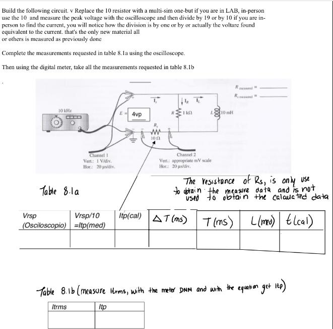
Build the following circuit. v Replace the 10 resistor with a multi-sim one-but if you are in LAB, in-person use the 10 and measure the peak voltage with the oscilloscope and then divide by 19 or by 10 if you are in- person to find the current, you will notice how the division is by one or by or actually the voltare found equivalent to the current. that's the only new material all or others is measured as previously done Complete the measurements requested in table 8.1a using the oscilloscope. Then using the digital meter, take all the measurements requested in table 8.1b 10 kHz Table 8.1 a Channel I Vert: 1 V/div. Hor: 20 s/div. Vrsp Vrsp/10 (Osciloscopio) =ltp(med) E-4vp "F ww 100 10 Channel 2 Vert: appropriate mV scale Hor: 20 s/div. 10 mH Itp(cal) AT (ms) The resistance of Rs, is only use to obtain the measure data and is not used to obtain the calculated data L(med) Elcal) R R AT (ms) T(ms) Table 8.1b (measure Herms, with the meter DNM and with the equation get itp) Itrms Itp
Step by Step Solution
3.40 Rating (153 Votes )
There are 3 Steps involved in it
Solutions ROL It Here 1K given Let Diode Dis made up of silicon Since the di... View full answer

Get step-by-step solutions from verified subject matter experts