

Question: Configuring IP on all interfaces Device Interface IP Address Subnet Mask Description R1 S0/0/0 12.1.1.1 255.255.255.252 Link to R2 Fa0/0 192.168.10.1 255.255.255.0 Link to
Configuring IP on all interfaces
| Device | Interface | IP Address | Subnet Mask | Description |
R1 | S0/0/0 | 12.1.1.1 | 255.255.255.252 | Link to R2 |
| Fa0/0 | 192.168.10.1 | 255.255.255.0 | Link to Server | |
R2 | S0/0/0 | 12.1.1.2 | 255.255.255.252 | Link to R1 |
| S0/0/1 | 23.1.1.1 | 255.255.255.252 | Link to R3 | |
R3 | S0/0/0 | 34.1.1.1 | 255.255.255.252 | Link to R4 |
| S0/0/1 | 23.1.1.2 | 255.255.255.252 | Link to R2 | |
| Loopback | 192.168.30.1 | 255.255.255.0 | Loopback Address | |
| R4 | S0/0/0 | 34.1.1.2 | 255.255.255.252 | Link to R3 |
| Fa0/0 | 192.168.20.1 | 255.255.255.0 | Link to SW1 | |
| PC1 | F0 | 192.168.10.2 | 255.255.255.0 | |
| PC2 | F0 | 192.168.20.2 | 255.255.255.0 |
Objectives
- Verify connectivity among devices before firewall configuration.
- Use ACLs to ensure remote access to the routers is available only from management station PC2.
- Configure ACLs on R1 and R4 to mitigate attacks.
- Verify ACL functionality.
Introduction
Access to routers R1, R2, R3 and R4 should only be permitted from PC2, the management station. PC2 is also used for connectivity testing to PC1-SERVER, a server providing DNS, SMTP, FTP, and HTTPS services.
Standard operating procedure is to apply ACLs on edge routers to mitigate common threats based on source and/or destination IP address. In this activity, you create ACLs on edge routers R1 and R4 to achieve this goal. You then verify ACL functionality from internal and external hosts.
The routers have been pre-configured with the following:
- Enable password: ciscoenable
- Password for console: ciscoconsole
- Username for VTY lines: ssh
- Password for VTY lines: passssh
- IP addressing
- RIP routing
- Verify Basic Network Connectivity - 20points
Verify network connectivity prior to configuring the IP ACLs.
Step1. From the PC2 command prompt, ping the PC1-SERVER server.
Step2. From the PC2 command prompt, SSH to the router R3 Lo0 interface. Exit the SSH session.
Step 3. From PC2, open a web browser to the PC1-SERVER server (using the IP address : 192.168.10.2) to display the web page. Close the browser on PC2.
Step 4. From the PC1-SERVER server command prompt, ping PC2.
Question: Need help with command steps from 1 to 4.
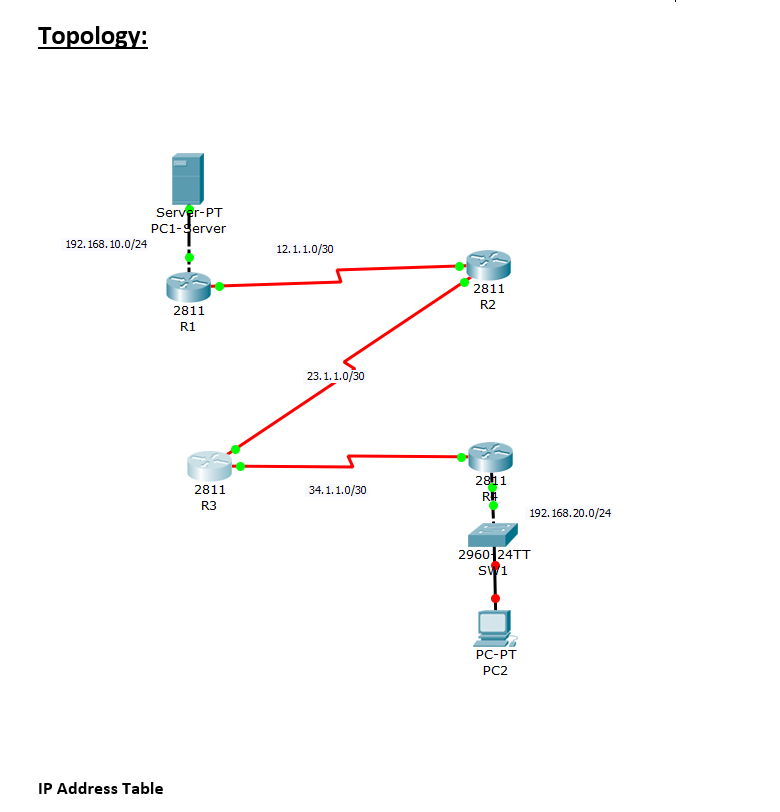
Topology: 192.168.10.0/24 Server-PT PC1-Server IP Address Table 2811 R1 2811 R3 12.1.1.0/30 23.1.1.0/30 34.1.1.0/30 2811 R2 2811 RE 192.168.20.0/24 2960 24TT SW1 PC-PT PC2
Step by Step Solution
There are 3 Steps involved in it

Get step-by-step solutions from verified subject matter experts