

Question: Consider a simple loopback system as in Fig. 1. In such a setup, a PC can send a message which is returned (looped) back to
Consider a simple loopback system as in Fig. 1. In such a setup, a PC can send a message which is returned (looped) back to PC by the processor. Such a loopback test is helpful to test if the processor is alive or not.
A PC (not shown) interfaces with PicoBlaze processor using an RS232 (serial) connection. Let us examine the case when the PC acts as a transmitter. In this case the data arrives serially on RS232_RX line. But we know that PicoBlaze accepts only byte-size data. So we need to convert the serial data into parallel (8-bit) data. In such a case, a UART (Universal Asynchronous Receiver Transmitter) block can help. UART_RX does the serial-to-parallel conversion i.e., the data arriving on RS232_RX line is buffered in a 16-byte buffer. Whenever new data is presented on rx_data output, UART_RX
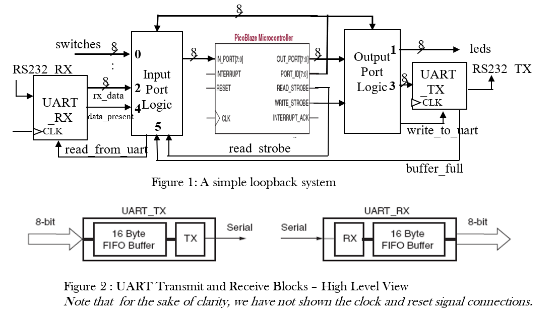
will assert data_present i.e., data_present = 1 in other words data_present validates rx_data. The Input Port Logic block consists of glue logic that connects UART_RX to the IN_PORT. After PicoBlaze reads the data, it can request the next data item by asserting read_from_uart signal.
Now, let us consider the case when PicoBlaze acts as a transmitter i.e., PC is the receiver. In this case, PicoBlaze puts out 8-bit data while PC is expecting serial data. Again, UART (UART_TX in Fig. 1) comes to our rescue! The output bus with id=3 is connected to UART_TX. Output Port Logic block interfaces PicoBlaze with leds and UART_TX.
In this system, we can also manually provide 8-bit data via 8 switches (switches bus in Fig. 1). PicoBlaze can write 8-bit data to drive 8 leds (leds bus in Fig. 1).
Recall that PicoBlaze can accept up to 256 input ports each of which can addressed by 8-bit PORT_ID bus. Similarly, it can drive up to 256 ports and the address of the port being driven appears on
PORT_ID bus. In Fig. 1, for example, the id of the input port, switches, is 0. Similarly, the rx_data has id of 2. The port ids are shown in bold font in the Fig.1. The high-level views of
UART in transmit and received modes are shown in Fig. 2.
Answer the following questions:
- (2 pts.) Explain under what condition(s) should the following signals be asserted?
- read_from_uart
- write_to_uart
- (4 pts.) cold_start: Write code to output a message Welcome to Loopback! to the serial port. You need encode the message in ASCII format. For ASCII table see http://www.asciitable.com Caution: UART_TX buffer size is only 16 bytes!!
- (4 pts.) led_echo: Write code to read switches and write it, inverted, to the LEDs.
- (5 pts.) rs232_echo: Write code to check if a byte has been received by UART_RX. If so, send it back to PC via UART_TX.
8 leds Output Port RS232 TX switches 8 0 RS232 RX : Input 2 Port UART 4 Logic RX data present 5 DCLK read from uart PicoBlaze Microcontroller 8 IN PORT(7:0) OUT_PORT|7:00 INTERRUPT PORT_10(7:0) RESET READ_STROBE WRITE STROBEH CLK INTERRUPT_ACK- Logic 3 UART TX DCLK IX data write to uart read strobe buffer full Figure 1: A simple loopback system UART_TX UART_RX 8-bit 8-bit Serial Serial 16 Byte FIFO Buffer TX RX 16 Byte FIFO Buffer Figure 2: UART Transmit and Receive Blocks - High Level View Note that for the sake of clarity, we have not shown the clock and reset signal connections
Step by Step Solution
There are 3 Steps involved in it

Get step-by-step solutions from verified subject matter experts