

Question: Consider an irregularly shaped object that the vice grip must be able to hold. Sketch this type of object of your choice. Modify the grips
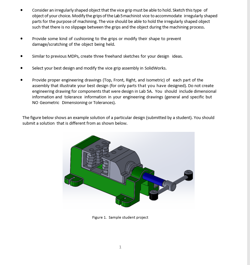
Consider an irregularly shaped object that the vice grip must be able to hold. Sketch this type of object of your choice. Modify the grips of the Lab 5 machinist vice to accommodate irregularly shaped parts for the purpose of machining. The vice should be able to hold the irregularly shaped object such that there is no slippage between the grips and the object during the machining process. Provide some kind of cushioning to the grips or modify their shape to prevent damage/scratching of the object being held. Similar to previous MDPs, create three freehand sketches for your design ideas. Select your best design and modify the vice grip assembly in SolidWorks. Provide proper engineering drawings (Top, Front, Right, and Isometric) of each part of the assembly that illustrate your best design (for only parts that you have designed). Do not create engineering drawing for components that were design in Lab 5A. You should include dimensional information and tolerance information in your engineering drawings (general and specific but NO Geometric Dimensioning or Tolerances). The figure below shows an example solution of a particular design (submitted by a student). You should submit a solution that is different from as shown below. CO OD Figure 1. Sample student project 1 Consider an irregularly shaped object that the vice grip must be able to hold. Sketch this type of object of your choice. Modify the grips of the Lab 5 machinist vice to accommodate irregularly shaped parts for the purpose of machining. The vice should be able to hold the irregularly shaped object such that there is no slippage between the grips and the object during the machining process. Provide some kind of cushioning to the grips or modify their shape to prevent damage/scratching of the object being held. Similar to previous MDPs, create three freehand sketches for your design ideas. Select your best design and modify the vice grip assembly in SolidWorks. Provide proper engineering drawings (Top, Front, Right, and Isometric) of each part of the assembly that illustrate your best design (for only parts that you have designed). Do not create engineering drawing for components that were design in Lab 5A. You should include dimensional information and tolerance information in your engineering drawings (general and specific but NO Geometric Dimensioning or Tolerances). The figure below shows an example solution of a particular design (submitted by a student). You should submit a solution that is different from as shown below. CO OD Figure 1. Sample student project 1
Step by Step Solution
There are 3 Steps involved in it

Get step-by-step solutions from verified subject matter experts