

Question: Consider the blending system shown in Fig.1. A feedback control system is used to control the product composition (x). Inlet flow rate (w2) is selected
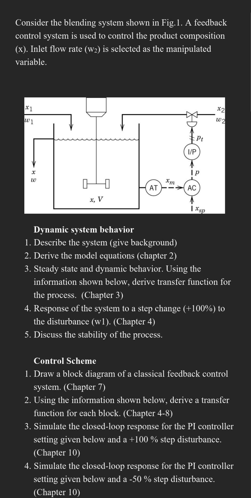
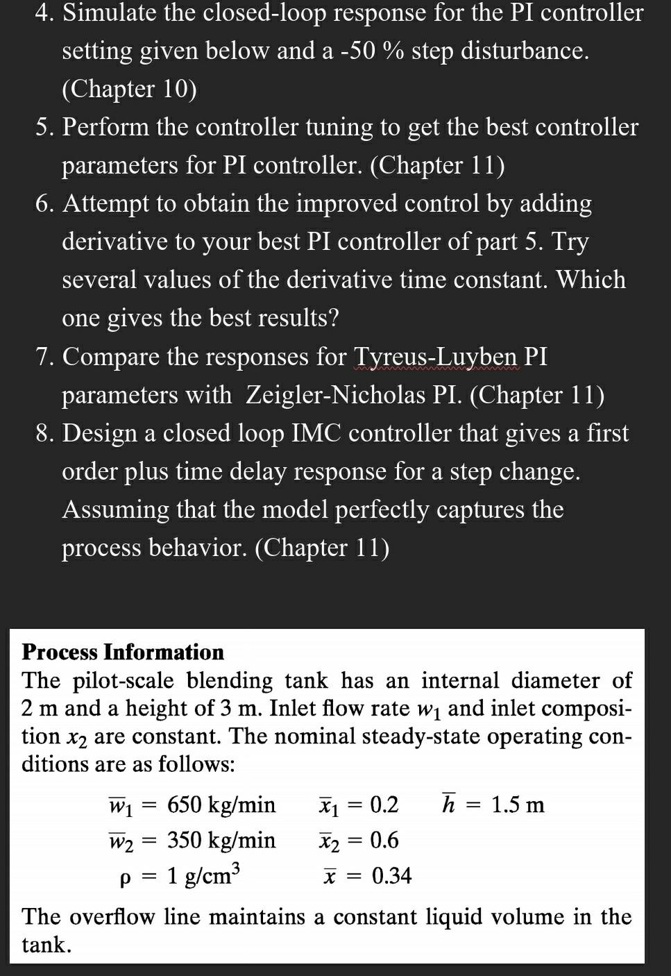
Consider the blending system shown in Fig.1. A feedback control system is used to control the product composition (x). Inlet flow rate (w2) is selected as the manipulated variable. Dynamic system behavior 1. Describe the system (give background) 2. Derive the model equations (chapter 2) 3. Steady state and dynamic behavior. Using the information shown below, derive transfer function for the process. (Chapter 3) 4. Response of the system to a step change (+100%) to the disturbance (w1). (Chapter 4) 5 . Discuss the stability of the process. Control Scheme 1. Draw a block diagram of a classical feedback control system. (Chapter 7) 2. Using the information shown below, derive a transfer function for each block. (Chapter 4-8) 3. Simulate the closed-loop response for the PI controller setting given below and a+100% step disturbance. (Chapter 10) 4. Simulate the closed-loop response for the PI controller setting given below and a 50% step disturbance. (Chapter 10) 4. Simulate the closed-loop response for the PI controller setting given below and a 50% step disturbance. (Chapter 10) 5. Perform the controller tuning to get the best controller parameters for PI controller. (Chapter 11) 6. Attempt to obtain the improved control by adding derivative to your best PI controller of part 5. Try several values of the derivative time constant. Which one gives the best results? 7. Compare the responses for Tyreus-Luyben PI parameters with Zeigler-Nicholas PI. (Chapter 11) 8. Design a closed loop IMC controller that gives a first order plus time delay response for a step change. Assuming that the model perfectly captures the process behavior. (Chapter 11) Process Information The pilot-scale blending tank has an internal diameter of 2m and a height of 3m. Inlet flow rate w1 and inlet composition x2 are constant. The nominal steady-state operating conditions are as follows: w1=650kg/minx1=0.2h=1.5mw2=350kg/minx2=0.6=1g/cm3x=0.34 The overflow line maintains a constant liquid volume in the tank
Step by Step Solution
There are 3 Steps involved in it

Get step-by-step solutions from verified subject matter experts