

Question: Consider the circuit shown below. In this circuit, we have four D flip-flops, and two 2-input XOR gates (shown as circles). This circuit is called
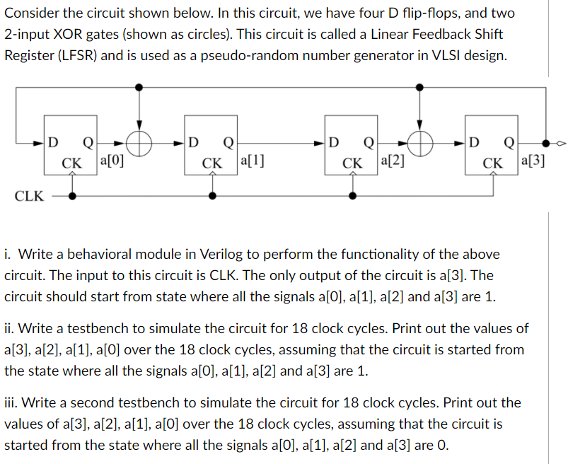
Consider the circuit shown below. In this circuit, we have four D flip-flops, and two 2-input XOR gates (shown as circles). This circuit is called a Linear Feedback Shift Register (LFSR) and is used as a pseudo-random number generator in VLSI design. D Q CK a[0] D Q CK a[1] D Q CK a[2] D Q CK a[3] CLK i. Write a behavioral module in Verilog to perform the functionality of the above circuit. The input to this circuit is CLK. The only output of the circuit is a[3]. The circuit should start from state where all the signals a[0], a[1], a[2] and a[3] are 1. ii. Write a testbench to simulate the circuit for 18 clock cycles. Print out the values of a[3], a[2], a[1], a[O] over the 18 clock cycles, assuming that the circuit is started from the state where all the signals a[0], a[1], a[2] and a[3] are 1. iii. Write a second testbench to simulate the circuit for 18 clock cycles. Print out the values of a[3], a[2], a[1], a[0] over the 18 clock cycles, assuming that the circuit is started from the state where all the signals a[0], a[1], a[2] and a[3] are 0. Consider the circuit shown below. In this circuit, we have four D flip-flops, and two 2-input XOR gates (shown as circles). This circuit is called a Linear Feedback Shift Register (LFSR) and is used as a pseudo-random number generator in VLSI design. D Q CK a[0] D Q CK a[1] D Q CK a[2] D Q CK a[3] CLK i. Write a behavioral module in Verilog to perform the functionality of the above circuit. The input to this circuit is CLK. The only output of the circuit is a[3]. The circuit should start from state where all the signals a[0], a[1], a[2] and a[3] are 1. ii. Write a testbench to simulate the circuit for 18 clock cycles. Print out the values of a[3], a[2], a[1], a[O] over the 18 clock cycles, assuming that the circuit is started from the state where all the signals a[0], a[1], a[2] and a[3] are 1. iii. Write a second testbench to simulate the circuit for 18 clock cycles. Print out the values of a[3], a[2], a[1], a[0] over the 18 clock cycles, assuming that the circuit is started from the state where all the signals a[0], a[1], a[2] and a[3] are 0
Step by Step Solution
There are 3 Steps involved in it

Get step-by-step solutions from verified subject matter experts