

Question: Consider the drawing Figure 2 and Figure 3 shown below. The drawing in Fig. 2 shows a tension element with a bolted connection to a
Consider the drawing Figure and Figure shown below. The drawing in Fig. shows a tension
element with a bolted connection to a thick gusset plate. The gusset plate is welded to
an end plate with EXX welding electrodes. Assume a fix connection at the bottom of the
columns to the ground and at the connection of roof truss to the columns. Use the information
above and answer the following:
Determine the tensile capacity of the angles. Only consider the dominant load
combination.
Determine if the connection can resist the tensile force due to the loads applied by a
combination of imposed loads, permanent loads and wind loads that were calculated in
project
Determine the tensile capacity of the gusset plate.
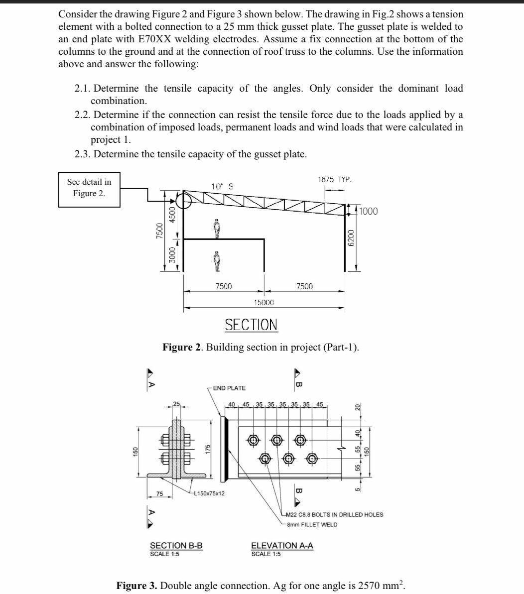
Figure Building section in project Part
Figure Double angle connection. Ag for one angle is
Step by Step Solution
There are 3 Steps involved in it
1 Expert Approved Answer
Step: 1 Unlock

Question Has Been Solved by an Expert!
Get step-by-step solutions from verified subject matter experts
Step: 2 Unlock
Step: 3 Unlock