

Question: Consider the electrical network shown below. The jagged lines correspond to resistors. The pair of parallel lines corresponds to a voltage source of e volts.
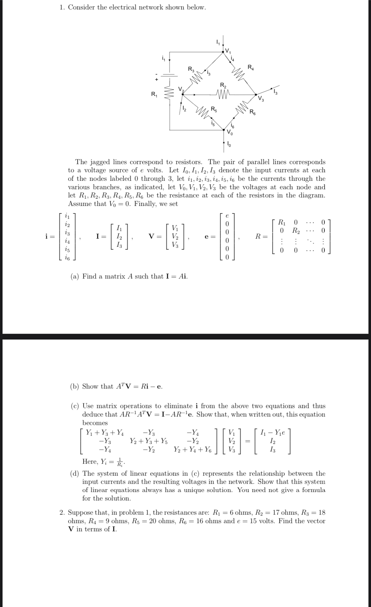
Consider the electrical network shown below.
The jagged lines correspond to resistors. The pair of parallel lines corresponds to a voltage source of volts. Let denote the input currents at each of the nodes labeled through let be the currents through the various branches, as indicated, let be the voltages at each node and let be the resistance at each of the resistors in the diagram. Assume that Finally, we set
a Find a matrix A such that
b Show that
c Use matrix operations to eliminate i from the above two equations and thus deduce that Show that, when written out, this equation becomes
Here,
d The system of linear equations in c represents the relationship between the input currents and the resulting voltages in the network. Show that this system of linear equations always has a unique solution. You need not give a formula for the solution.
Suppose that, in problem the resistances are: ohms, ohms, ohms, ohms, ohms, ohms and volts. Find the vector in terms of I.
Explain in detail part step by step on how you achieve the answer
Step by Step Solution
There are 3 Steps involved in it
1 Expert Approved Answer
Step: 1 Unlock

Question Has Been Solved by an Expert!
Get step-by-step solutions from verified subject matter experts
Step: 2 Unlock
Step: 3 Unlock