

Question: Consider the following assembly language code: I0: add SR3.SR1,SRO; ADD R3-R1RO I1: Iw SR2.200(SRI): IILDW R2- MEMIRI+100] 12: bez SR4 ,R2,Label1 13: sw R2, 100(SR4);
![I1: Iw SR2.200(SRI): IILDW R2- MEMIRI+100] 12: bez SR4 ,R2,Label1 13: sw](https://dsd5zvtm8ll6.cloudfront.net/si.experts.images/questions/2024/09/66f0bff9f0ecd_81766f0bff98f6d1.jpg)
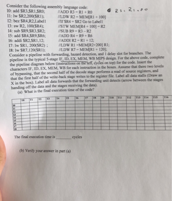
Consider the following assembly language code: I0: add SR3.SR1,SRO; ADD R3-R1RO I1: Iw SR2.200(SRI): IILDW R2- MEMIRI+100] 12: bez SR4 ,R2,Label1 13: sw R2, 100(SR4); nf SR4-SR2 Go to Labell /STW MEMIR4+100] R2 SUB R9-R3-R2 14: sub SR9,SR3,SR2; 15: add SR4,SR9,SR6; ADD R4-R9+ R6 16: addi SR2,SR1,12; 17: lw SR1, 200(SR2)/LDW R1-MEMIR2+200]RI 18: lw SR7,120(SR1); Consider a pipeline with forwarding, hazard detection, and 1 delay slot for branches. The pipeline is the typical s-stage IF. ID, EX, MEM. WB MIPS design. For the above code, complete the pipeline diagram below (instructions on the left, cycles on top) for the code. Insert the characters IF, ID, EX, MEM, WB for each instruction in the boxes. Assume that there two levels of bypassing, that the second half of the decode stage performs a read of source registers, and that the first half of the write-back stage writes to the X in the box). Label all data forwards handing off the data and the stages receiving the data). //ADDI R2 = Ri +12; LDW R7-MEMIRI+120] register file. Label all data stalls (Draw an that the forwarding unit detects (arrow between the stages (a) What is the final execution time of the code? T16 TS 10 12 14 15 17 18 The final execution time is cycles (b) Verify your answer in part (a)
Step by Step Solution
There are 3 Steps involved in it

Get step-by-step solutions from verified subject matter experts