

Question: Consider the interconnected LAN structure shown in Figure 4.8. Assume that hosts 1 through 5, respectively, are assigned the following MAC addresses: 00-40-33-40-1B-2C, 00-40-33-25-85-BB, 00-40-33-25-85-BC,
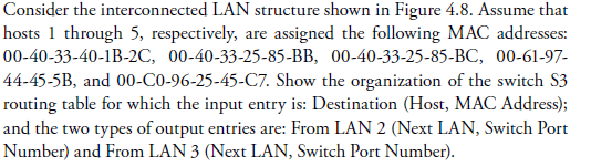
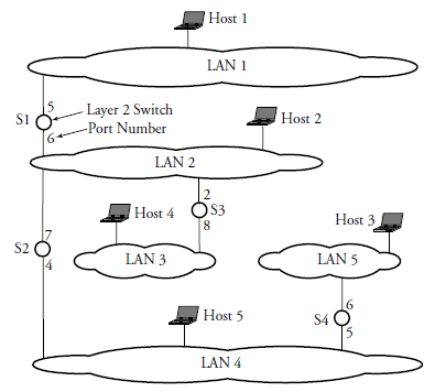
Consider the interconnected LAN structure shown in Figure 4.8. Assume that hosts 1 through 5, respectively, are assigned the following MAC addresses: 00-40-33-40-1B-2C, 00-40-33-25-85-BB, 00-40-33-25-85-BC, 00-61-97 44-45-5B, and 00-C0-96-25-45-C7. Show the organization of the switch S3 routing table for which the input entry is: Destination (Host, MAC Address); and the two types of output entries are: From LAN 2 (Next LAN, Switch Port Number) and From LAN 3 (Next LAN, Switch Port Number). Consider the interconnected LAN structure shown in Figure 4.8. Assume that hosts 1 through 5, respectively, are assigned the following MAC addresses: 00-40-33-40-1B-2C, 00-40-33-25-85-BB, 00-40-33-25-85-BC, 00-61-97 44-45-5B, and 00-C0-96-25-45-C7. Show the organization of the switch S3 routing table for which the input entry is: Destination (Host, MAC Address); and the two types of output entries are: From LAN 2 (Next LAN, Switch Port Number) and From LAN 3 (Next LAN, Switch Port Number)
Step by Step Solution
There are 3 Steps involved in it

Get step-by-step solutions from verified subject matter experts