

Question: Consider the mechanical system given in Figure 2 . d 1 ( t ) and d 2 ( t ) are the displacements of the
Consider the mechanical system given in Figure and are the displacements of the Consider the mechanical system given in Figure and are the displacements of the
two blocks with respect to their nominal positions when no any force exist and are
the velocities of the two blocks, respectively.
Figure Mechanical System
two blocks with respect to their nominal positions when no any force exist and are
the velocities of the two blocks, respectively.
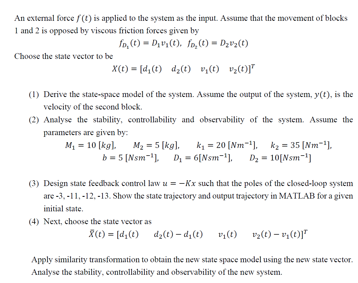
Figure Mechanical SystemAn external force is applied to the system as the input. Assume that the movement of blocks
and is opposed by viscous friction forces given by
Choose the state vector to be
Derive the statespace model of the system. Assume the output of the system, is the
velocity of the second block.
Analyse the stability, controllability and observability of the system. Assume the
parameters are given by:
Design state feedback control law such that the poles of the closedloop system
are Show the state trajectory and output trajectory in MATLAB for a given
initial state.
Next, choose the state vector as
Apply similarity transformation to obtain the new state space model using the new state vector.
Analyse the stability, controllability and observability of the new system.
Step by Step Solution
There are 3 Steps involved in it
1 Expert Approved Answer
Step: 1 Unlock

Question Has Been Solved by an Expert!
Get step-by-step solutions from verified subject matter experts
Step: 2 Unlock
Step: 3 Unlock