

Question: Consider the mechanical system shown in Figure 1 . Two identical cylindrical rollers of mass m and radius r are fixed at their centres. They
Consider the mechanical system shown in Figure Two identical cylindrical rollers of mass
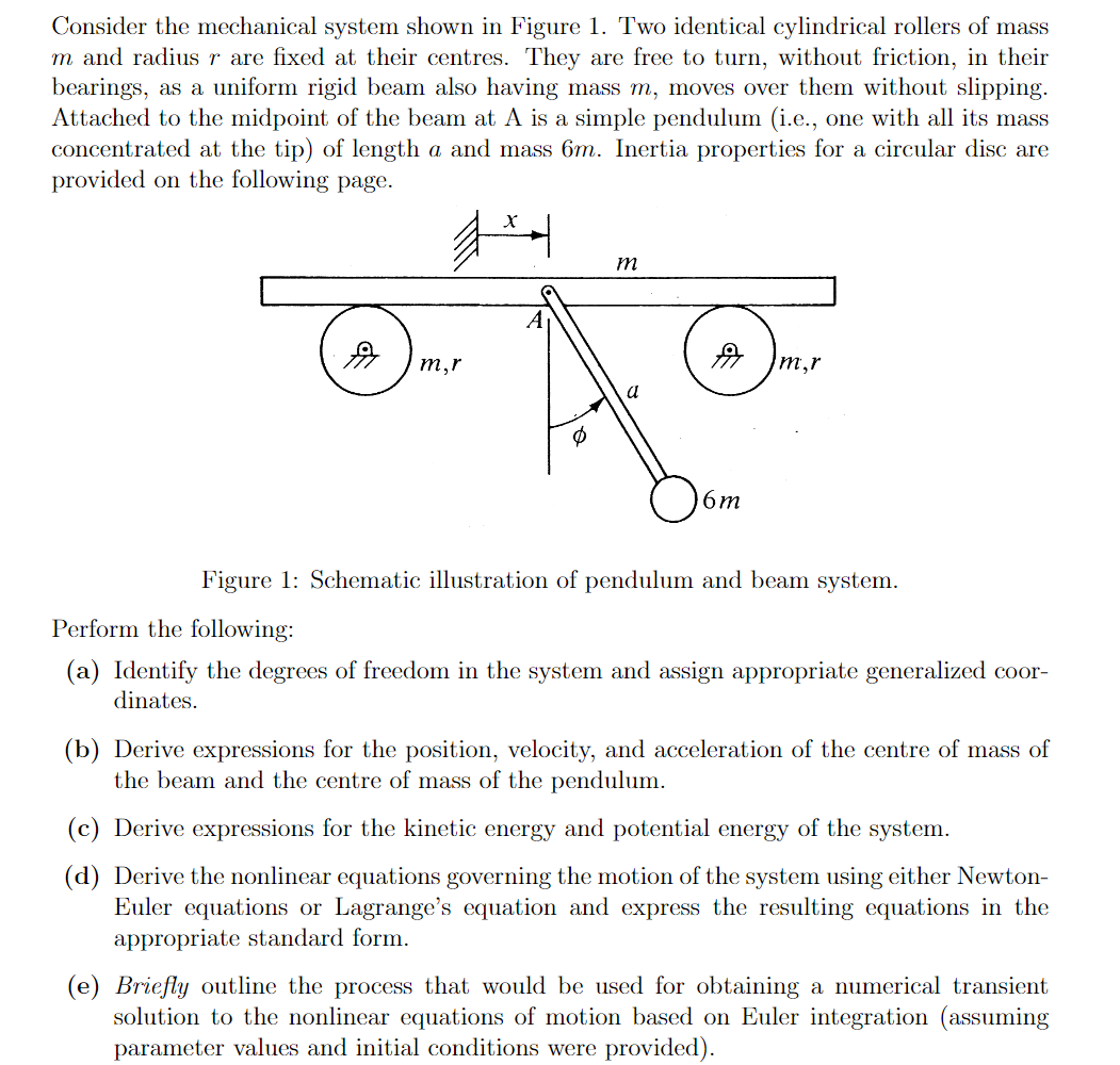
and radius are fixed at their centres. They are free to turn, without friction, in their
bearings, as a uniform rigid beam also having mass moves over them without slipping.
Attached to the midpoint of the beam at A is a simple pendulum ie one with all its mass
concentrated at the tip of length a and mass Inertia properties for a circular disc are
provided on the following page.
Figure : Schematic illustration of pendulum and beam system.
Perform the following:
a Identify the degrees of freedom in the system and assign appropriate generalized coor
dinates.
b Derive expressions for the position, velocity, and acceleration of the centre of mass of
the beam and the centre of mass of the pendulum.
c Derive expressions for the kinetic energy and potential energy of the system.
d Derive the nonlinear equations governing the motion of the system using either Newton
Euler equations or Lagrange's equation and express the resulting equations in the
appropriate standard form.
e Briefly outline the process that would be used for obtaining a numerical transient
solution to the nonlinear equations of motion based on Euler integration assuming
parameter values and initial conditions were provided
Step by Step Solution
There are 3 Steps involved in it
1 Expert Approved Answer
Step: 1 Unlock

Question Has Been Solved by an Expert!
Get step-by-step solutions from verified subject matter experts
Step: 2 Unlock
Step: 3 Unlock